Advertisements
Advertisements
प्रश्न
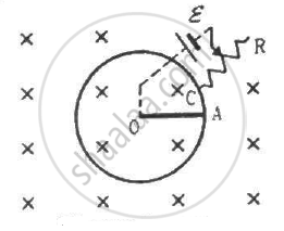
Suppose the circular loop lies in a vertical plane. The rod has a mass m. The rod and the loop have negligible resistances but the wire connecting O and C has a resistance R. The rod is made to rotate with a uniform angular velocity ω in the clockwise direction by applying a force at the midpoint of OA in a direction perpendicular to it. A battery of emf ε and a variable resistance R are connected between O and C. Neglect the resistance of the connecting wires. Let θ be the angle made by the rod from the horizontal position (show in the figure), measured in the clockwise direction. During the part of the motion 0 < θ < π/4 the only forces acting on the rod are gravity and the forces exerted by the magnetic field and the pivot. However, during the part of the motion, the resistance R is varied in such a way that the rod continues to rotate with a constant angular velocity ω. Find the value of R in terms of the given quantities.
उत्तर
It is given that the rod is rotated with angular speed in clockwise direction.
The emf induced in the rod (e) is `(Bomegaa^2)/2,` with O at the lower potential and A at the higher potential.
The equivalent circuit can be drawn as:-
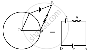
\[i = \frac{e + E}{R} = \frac{\frac{1}{2}B\omega a^2 + E}{R}\]
\[ = \frac{B\omega a^2 + 2E}{2R}\]
Because the rod rotates with uniform angular velocity, the net torque about point O is zero.
Now,
Net force on the rod, Fnet = mg cos θ - ilB
Net torque, τ = (mg cos θ - ilB).(r/2) = 0
∴ mg cos θ = ilB
\[R = \frac{(B\omega a^2 + 2E)}{2R}(a \times B)\]
\[ \Rightarrow R = \frac{(B\omega a^2 + 2E)aB}{2mg \cos \theta}\]
APPEARS IN
संबंधित प्रश्न
The current flowing through an inductor of self-inductance L is continuously increasing. Plot a graph showing the variation of
Induced emf versus dI/dt
Figure shows a metal rod PQ resting on the smooth rails AB and positioned between the poles of a permanent magnet. The rails, the rod, and the magnetic field are in three mutual perpendicular directions. A galvanometer G connects the rails through a switch K. Length of the rod = 15 cm, B = 0.50 T, resistance of the closed loop containing the rod = 9.0 mΩ. Assume the field to be uniform.
(a) Suppose K is open and the rod is moved with a speed of 12 cm s−1 in the direction shown. Give the polarity and magnitude of the induced emf.
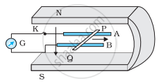
(b) Is there an excess charge built up at the ends of the rods when K is open? What if K is closed?
(c) With K open and the rod moving uniformly, there is no net force on the electrons in the rod PQ even though they do experience magnetic force due to the motion of the rod. Explain.
(d) What is the retarding force on the rod when K is closed?
(e) How much power is required (by an external agent) to keep the rod moving at the same speed = (12 cm s−1) when K is closed? How much power is required when K is open?
(f) How much power is dissipated as heat in the closed circuit? What is the source of this power?
(g) What is the induced emf in the moving rod if the magnetic field is parallel to the rails instead of being perpendicular?
A metallic rod of length ‘l’ is rotated with a frequency v with one end hinged at the centre and the other end at the circumference of a circular metallic ring of radius r, about an axis passing through the centre and perpendicular to the plane of the ring. A constant uniform magnetic field B parallel to the axis is present everywhere. Using Lorentz force, explain how emf is induced between the centre and the metallic ring and hence obtained the expression for it.
Consider the situation shown in figure. The wire AB is slid on the fixed rails with a constant velocity. If the wire AB is replaced by a semicircular wire, the magnitude of the induced current will _____________ .

A small, conducting circular loop is placed inside a long solenoid carrying a current. The plane of the loop contains the axis of the solenoid. If the current in the solenoid is varied, the current induced in the loop is __________________ .
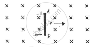
A rod AB moves with a uniform velocity v in a uniform magnetic field as shown in figure.
A conducting circular loop having a radius of 5.0 cm, is placed perpendicular to a magnetic field of 0.50 T. It is removed from the field in 0.50 s. Find the average emf produced in the loop during this time.
Figure shows a conducting square loop placed parallel to the pole-faces of a ring magnet. The pole-faces have an area of 1 cm2 each and the field between the poles is 0.10 T. The wires making the loop are all outside the magnetic field. If the magnet is removed in 1.0 s, what is the average emf induced in the loop?
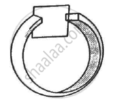
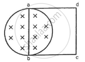
A uniform magnetic field B exists in a cylindrical region of radius 10 cm as shown in figure. A uniform wire of length 80 cm and resistance 4.0 Ω is bent into a square frame and is placed with one side along a diameter of the cylindrical region. If the magnetic field increases at a constant rate of 0.010 T/s, find the current induced in the frame.
A metallic metre stick moves with a velocity of 2 m s−1 in a direction perpendicular to its length and perpendicular to a uniform magnetic field of magnitude 0.2 T. Find the emf induced between the ends of the stick.
A circular copper-ring of radius r translates in its plane with a constant velocity v. A uniform magnetic field B exists in the space in a direction perpendicular to the plane of the ring. Consider different pairs of diametrically opposite points on the ring. (a) Between which pair of points is the emf maximum? What is the value of this maximum emf? (b) Between which pair of points is the emf minimum? What is the value of this minimum emf ?
Figure shows a long U-shaped wire of width l placed in a perpendicular magnetic field B. A wire of length l is slid on the U-shaped wire with a constant velocity v towards right. The resistance of all the wires is r per unit length. At t = 0, the sliding wire is close to the left edge of the U-shaped wire. Draw an equivalent circuit diagram, showing the induced emf as a battery. Calculate the current in the circuit.
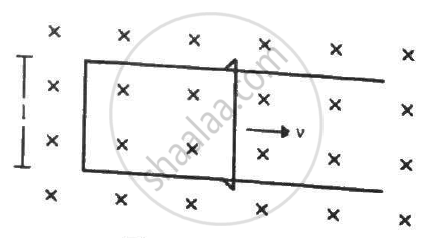
A conducting wire ab of length l, resistance r and mass m starts sliding at t = 0 down a smooth, vertical, thick pair of connected rails as shown in figure. A uniform magnetic field B exists in the space in a direction perpendicular to the plane of the rails. (a) Write the induced emf in the loop at an instant t when the speed of the wire is v. (b) What would be the magnitude and direction of the induced current in the wire? (c) Find the downward acceleration of the wire at this instant. (d) After sufficient time, the wire starts moving with a constant velocity. Find this velocity vm. (e) Find the velocity of the wire as a function of time. (f) Find the displacement of the wire as a function of time. (g) Show that the rate of heat developed in the wire is equal to the rate at which the gravitational potential energy is decreased after steady state is reached.
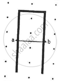
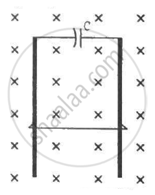
A wire of mass m and length l can slide freely on a pair of smooth, vertical rails (figure). A magnetic field B exists in the region in the direction perpendicular to the plane of the rails. The rails are connected at the top end by a capacitor of capacitance C. Find the acceleration of the wire neglecting any electric resistance.
The current in a solenoid of 240 turns, having a length of 12 cm and a radius of 2 cm, changes at a rate of 0.8 A s−1. Find the emf induced in it.
An inductor-coil of inductance 20 mH having resistance 10 Ω is joined to an ideal battery of emf 5.0 V. Find the rate of change of the induced emf at (a) t = 0, (b) t = 10 ms and (c) t = 1.0 s.
The mutual inductance between two coils is 2.5 H. If the current in one coil is changed at the rate of 1 As−1, what will be the emf induced in the other coil?
A small flat search coil of area 5cm2 with 140 closely wound turns is placed between the poles of a powerful magnet producing magnetic field 0.09T and then quickly removed out of the field region. Calculate:
(a) Change of magnetic flux through the coil, and
(b) emf induced in the coil.
An alternating emf of 110 V is applied to a circuit containing a resistance R of 80 Ω and an inductor L in series. The current is found to lag behind the supply voltage by an angle 8 = tan-1 (3/4). Find the :
(i) Inductive reactance
(ii) Impedance of the circuit
(iii) Current flowing in the circuit
(iv) If the inductor has a coefficient of self-inductance of 0.1 H, what is the frequency of the applied emf?
