Advertisements
Advertisements
प्रश्न
A coil having an inductance L and a resistance R is connected to a battery of emf ε. Find the time taken for the magnetic energy stored in the circuit to change from one fourth of the steady-state value to half of the steady-state value.
उत्तर
Given:-
Emf of the battery = ε
Inductance of the inductor = L
Resistance = R
Maximum current in the coil `= epsilon/R`
At the steady state, current in the coil, `i =epsilon/R.`
The magnetic field energy stored at the steady state is given by
\[U = \frac{1}{2}L i^2\text{ or } U\]
\[= \frac{\epsilon^2}{2 R^2}L\]
One-fourth of the steady-state value of the magnetic energy is given by
\[U' = \frac{1}{8}L\frac{E^2}{R^2}\]
Half of the value of the steady-state energy \[=\frac{1}{4}L\frac{E^2}{R^2}\]
Let the magnetic energy reach one-fourth of its steady-state value in time t1 and let it reach half of its value in time t2.
Now,
\[\frac{1}{8}L\frac{E^2}{R^2} = \frac{1}{2}L\frac{E^2}{R^2}(1 - e^{- t_1 R/L} )^2 \]
\[ \Rightarrow 1 - e^{- t_1 R/L} = \frac{1}{2}\]
\[ \Rightarrow t_1 \frac{R}{L} = \ln 2\]
And,
\[\frac{1}{4}L\frac{E^2}{R^2} = \frac{1}{2}L\frac{E^2}{R^2}(1 - e^{- t_2 R/L} )^2 \]
\[ \Rightarrow e^{- t_2 R/L} = \frac{\sqrt{2} - 1}{\sqrt{2}} = \frac{2 - \sqrt{2}}{2}\]
\[ \Rightarrow t_1 = \tau \ln\left( \frac{1}{2 - \sqrt{2}} \right) + \ln 2\]
Thus, the time taken by the magnetic energy stored in the circuit to change from one-fourth of its steady-state value to half of its steady-state value is given by
\[t_2 - t_1 = \tau \ln\frac{1}{2 - \sqrt{2}}\]
APPEARS IN
संबंधित प्रश्न
Define 'quality factor' of resonance in a series LCR circuit. What is its SI unit?
In a series LCR circuit, obtain the condition under which watt-less current flows in the circuit ?
Show that in an a.c. circuit containing a pure inductor, the voltage is ahead of current by π/2 in phase ?
A series LCR circuit is connected to a source having voltage v = vm sin ωt. Derive the expression for the instantaneous current I and its phase relationship to the applied voltage.
Obtain the condition for resonance to occur. Define ‘power factor’. State the conditions under which it is (i) maximum and (ii) minimum.
An L-R circuit has L = 1.0 H and R = 20 Ω. It is connected across an emf of 2.0 V at t = 0. Find di/dt at (a) t = 100 ms, (b) t = 200 ms and (c) t = 1.0 s.
Answer the following question.
What is the phase difference between the voltages across the inductor and the capacitor at resonance in the LCR circuit?
Answer the following question.
Draw the diagram of a device that is used to decrease high ac voltage into a low ac voltage and state its working principle. Write four sources of energy loss in this device.
Figure shows a series LCR circuit connected to a variable frequency 230 V source. L = 5.0 H, C = 80 µF, R = 40 Ω.

- Determine the source frequency which drives the circuit in resonance.
- Obtain the impedance of the circuit and the amplitude of current at the resonating frequency.
- Determine the rms potential drops across the three elements of the circuit. Show that the potential drop across the LC combination is zero at the resonating frequency.
In a series LCR circuit supplied with AC, ______.
In an L.C.R. series a.c. circuit, the current ______.
If an LCR series circuit is connected to an ac source, then at resonance the voltage across ______.
A coil of 40 henry inductance is connected in series with a resistance of 8 ohm and the combination is joined to the terminals of a 2 volt battery. The time constant of the circuit is ______.
A series LCR circuit containing 5.0 H inductor, 80 µF capacitor and 40 Ω resistor is connected to 230 V variable frequency ac source. The angular frequencies of the source at which power transferred to the circuit is half the power at the resonant angular frequency are likely to be ______.
A coil of 0.01 henry inductance and 1 ohm resistance is connected to 200 volt, 50 Hz ac supply. Find the impedance of the circuit and time lag between max. alternating voltage and current.
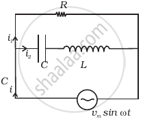
Consider the LCR circuit shown in figure. Find the net current i and the phase of i. Show that i = v/Z`. Find the impedance Z for this circuit.

A series LCR circuit driven by 300 V at a frequency of 50 Hz contains a resistance R = 3 kΩ, an inductor of inductive reactance XL = 250 πΩ, and an unknown capacitor. The value of capacitance to maximize the average power should be ______.
A series RL circuit with R = 10 Ω and L = `(100/pi)` mH is connected to an ac source of voltage V = 141 sin (100 πt), where V is in volts and t is in seconds. Calculate
- the impedance of the circuit
- phase angle, and
- the voltage drop across the inductor.
Draw the phasor diagram for a series LRC circuit connected to an AC source.
