Advertisements
Advertisements
प्रश्न
An LR circuit having a time constant of 50 ms is connected with an ideal battery of emf ε. find the time elapsed before (a) the current reaches half its maximum value, (b) the power dissipated in heat reaches half its maximum value and (c) the magnetic field energy stored in the circuit reaches half its maximum value.
उत्तर
Given:-
Time constant of the LR circuit = 50 ms
Emf of the battery = ε
The time constant of the LR circuit is given by
\[\tau = \frac{L}{R} = 50 ms = 0 . 05 s\]
Let the current reach half of its maximum value in time t.
Now,
\[\frac{i_0}{2} = i_0 (1 - e^{- t/0 . 05} )\]
\[ \Rightarrow \frac{1}{2} = 1 - e^{- t/0 . 05} \]
\[ \Rightarrow e^{- t/0 . 03} = \frac{1}{2}\]
On taking natural logarithm (ln) on both sides, we get
\[\ln e^{- t/0 . 05} = \ln\left( \frac{1}{2} \right)\]
\[ \Rightarrow - \frac{t}{0 . 05} = \ln(1) - \ln(2)\]
\[ \Rightarrow - \frac{t}{0 . 05} = 0 - 0.6931\]
\[ \Rightarrow t = 0 . 05 \times 0 . 6931\]
\[ = 0 . 03465 s\]
\[ = 35 ms\]
(b) Let t be the time at which the power dissipated is half its maximum value.
Maximum power = `E^2/R`
\[\therefore \frac{E^2}{2R} = \frac{E^2}{R}(1 - e^{tR/L} )^2 \]
\[ \Rightarrow 1 - e^{- R/L} = \frac{1}{\sqrt{2}} = 0 . 707\]
\[ \Rightarrow e^{- tR/L} = 0 . 293\]
\[ \Rightarrow t = 50 \times 1 . 2275 ms\]
\[ = 61 . 2 ms\]
(c) Current in the coil at the steady state, `i = epsilon/R`
Magnetic field energy stored at the steady state,
\[U = \frac{1}{2}L i^2\text{ or }U\]
\[= \frac{\epsilon^2}{2 R^2}L\]
Half of the value of the steady-state energy = \[\frac{1}{4}L\frac{\epsilon^2}{R^2}\]
Now,
\[\frac{1}{4}L\frac{\epsilon^2}{R^2} = \frac{1}{2}L\frac{\epsilon^2}{R^2}(1 - e^{- tR/L} )^2 \]
\[ \Rightarrow e^{- tR/L} = \frac{\sqrt{2} - 1}{\sqrt{2}} = \frac{2 - \sqrt{2}}{2}\]
\[ \Rightarrow t = \tau\left[ \ln\left( \frac{1}{2 - \sqrt{2}} \right) + \ln 2 \right]\]
\[= 0 . 05\left[ \ln\left( \frac{1}{2 - \sqrt{2}} \right) + \ln 2 \right]\]
\[= 0 . 061 s\]
\[= 61 ms\]
APPEARS IN
संबंधित प्रश्न
In a series LCR circuit connected to an a.c. source of voltage v = vmsinωt, use phasor diagram to derive an expression for the current in the circuit. Hence, obtain the expression for the power dissipated in the circuit. Show that power dissipated at resonance is maximum
Derive an expression for the average power consumed in a series LCR circuit connected to a.c. source in which the phase difference between the voltage and the current in the circuit is Φ.
A solenoid having inductance 4.0 H and resistance 10 Ω is connected to a 4.0 V battery at t = 0. Find (a) the time constant, (b) the time elapsed before the current reaches 0.63 of its steady-state value, (c) the power delivered by the battery at this instant and (d) the power dissipated in Joule heating at this instant.
Two coils A and B have inductances 1.0 H and 2.0 H respectively. The resistance of each coil is 10 Ω. Each coil is connected to an ideal battery of emf 2.0 V at t = 0. Let iA and iBbe the currents in the two circuit at time t. Find the ratio iA / iB at (a) t = 100 ms, (b) t = 200 ms and (c) t = 1 s.
(i) An a.c. source of emf ε = 200 sin omegat is connected to a resistor of 50 Ω . calculate :
(1) Average current (`"I"_("avg")`)
(2) Root mean square (rms) value of emf
(ii) State any two characteristics of resonance in an LCR series circuit.
What will be the potential difference in the circuit when direct current is passed through the circuit?

Derive an expression for the average power dissipated in a series LCR circuit.
Keeping the source frequency equal to the resonating frequency of the series LCR circuit, if the three elements, L, C and R are arranged in parallel, show that the total current in the parallel LCR circuit is minimum at this frequency. Obtain the current rms value in each branch of the circuit for the elements and source specified for this frequency.
For a series LCR-circuit, the power loss at resonance is ______.
In an L.C.R. series a.c. circuit, the current ______.
If an LCR series circuit is connected to an ac source, then at resonance the voltage across ______.
In an LCR series a.c. circuit, the voltage across each of the components, L, C and R is 50V. The voltage across the LC combination will be ______.
At resonance frequency the impedance in series LCR circuit is ______.
A series LCR circuit contains inductance 5 mH, capacitance 2µF and resistance ion. If a frequency A.C. source is varied, what is the frequency at which maximum power is dissipated?
The phase diffn b/w the current and voltage at resonance is
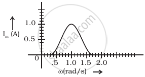
In series LCR circuit, the plot of Imax vs ω is shown in figure. Find the bandwidth and mark in the figure.

When an alternating voltage of 220V is applied across device X, a current of 0.25A flows which lags behind the applied voltage in phase by π/2 radian. If the same voltage is applied across another device Y, the same current flows but now it is in phase with the applied voltage.
- Name the devices X and Y.
- Calculate the current flowing in the circuit when the same voltage is applied across the series combination of X and Y.
A series LCR circuit is connected to an ac source. Using the phasor diagram, derive the expression for the impedance of the circuit.
