Advertisements
Advertisements
प्रश्न
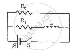
Consider the circuit shown in figure. (a) Find the current through the battery a long time after the switch S is closed. (b) Suppose the switch is again opened at t = 0. What is the time constant of the discharging circuit? (c) Find the current through the inductor after one time constant.

उत्तर
(a) Because the switch is closed, the battery gets connected across the L‒R circuit.
The current in the L‒R circuit after t seconds after connecting the battery is given by
i = i0 (1 − e−t/τ)
Here,
i0 = Steady state current
τ = Time constant = `L/R`
After a long time, t → ∞.
Now,
Current in the inductor, i = i0 (1 − e0) = 0
Thus, the effect of inductance vanishes.
\[i = \frac{\epsilon}{R_{net}}\]
\[i = \frac{\epsilon}{\frac{R_1 \times R_2}{R_1 + R_2}} = \frac{\epsilon( R_1 + R_2 )}{R_1 R_2}\]
(b) When the switch is opened, the resistance are in series.
The time constant is given by
\[\tau = \frac{L}{R_{net}} = \frac{L}{R_1 + R_2}\]
(c) The inductor will discharge through resistors R1 and R2.
The current through the inductor after one time constant is given by
t = τ
∴ Current, i = i0 e−τ/τ
Here,
\[i_0=\frac{\epsilon}{R_1 + R_2}\]
\[\therefore i=\frac{\epsilon}{R_1 + R_2} \times \frac{1}{e}\]
APPEARS IN
संबंधित प्रश्न
Why does current in a steady state not flow in a capacitor connected across a battery? However momentary current does flow during charging or discharging of the capacitor. Explain.
Show that in an a.c. circuit containing a pure inductor, the voltage is ahead of current by π/2 in phase ?
Find the value of t/τ for which the current in an LR circuit builds up to (a) 90%, (b) 99% and (c) 99.9% of the steady-state value.
The time constant of an LR circuit is 40 ms. The circuit is connected at t = 0 and the steady-state current is found to be 2.0 A. Find the current at (a) t = 10 ms (b) t = 20 ms, (c) t = 100 ms and (d) t = 1 s.
An inductor-coil of resistance 10 Ω and inductance 120 mH is connected across a battery of emf 6 V and internal resistance 2 Ω. Find the charge which flows through the inductor in (a) 10 ms, (b) 20 ms and (c) 100 ms after the connections are made.
A solenoid having inductance 4.0 H and resistance 10 Ω is connected to a 4.0 V battery at t = 0. Find (a) the time constant, (b) the time elapsed before the current reaches 0.63 of its steady-state value, (c) the power delivered by the battery at this instant and (d) the power dissipated in Joule heating at this instant.
Two coils A and B have inductances 1.0 H and 2.0 H respectively. The resistance of each coil is 10 Ω. Each coil is connected to an ideal battery of emf 2.0 V at t = 0. Let iA and iBbe the currents in the two circuit at time t. Find the ratio iA / iB at (a) t = 100 ms, (b) t = 200 ms and (c) t = 1 s.
The current in a discharging LR circuit without the battery drops from 2.0 A to 1.0 A in 0.10 s. (a) Find the time constant of the circuit. (b) If the inductance of the circuit 4.0 H, what is its resistance?
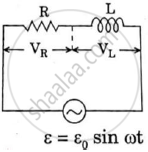
An ac circuit as shown in the figure has an inductor of inductance L and a resistor or resistance R connected in series. Using the phasor diagram, explain why the voltage in the circuit will lead the current in phase.
What will be the potential difference in the circuit when direct current is passed through the circuit?

In a series, LCR circuit, obtain an expression for the resonant frequency,
Derive an expression for the average power dissipated in a series LCR circuit.
Obtain the resonant frequency and Q-factor of a series LCR circuit with L = 3.0 H, C = 27 µF, and R = 7.4 Ω. It is desired to improve the sharpness of the resonance of the circuit by reducing its ‘full width at half maximum’ by a factor of 2. Suggest a suitable way.
In series combination of R, L and C with an A.C. source at resonance, if R = 20 ohm, then impedence Z of the combination is ______.
In an LCR series a.c. circuit, the voltage across each of the components, L, C and R is 50V. The voltage across the LC combination will be ______.
The resonant frequency of a RF oscillator is 1 MHz and its bandwidth is 10 kHz. The quality factor will be :
To reduce the resonant frequency in an LCR series circuit with a generator ______.
Draw a labelled graph showing variation of impedance (Z) of a series LCR circuit Vs frequency (f) of the ac supply. Mark the resonant frequency as f0·
