Advertisements
Advertisements
प्रश्न
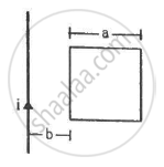
Figure shows a square frame of wire having a total resistance r placed coplanarly with a long, straight wire. The wire carries a current i given by i = i0 sin ωt. Find (a) the flux of the magnetic field through the square frame, (b) the emf induced in the frame and (c) the heat developed in the frame in the time interval 0 to \[\frac{20\pi}{\omega}.\]
उत्तर
Let us consider an element of the loop of length dx at a distance x from the wire.

(a) Area of the element of loop A = adx
Magnetic field at a distance x from the wire, `(20 pi)/omega`
The magnetic flux of the element is given by
`d phi = (mu_0i xx adx)/(2 pi x)`
The total flux through the frame is given by
`phi = intd phi`
= `int_b^(a + b) (mu_0iadx)/(2 pi x)`
= `(mu_0ia)/(2 pi) ln [1 + a/b]`
(b) The e.m.f. induced in the frame is given by
`d/dt (mu_0ia)/(2 pi) ln [1 + a/b]`
= `(mu_0a)/(2 pi) ln [1 + a/b] d/dt (i_0 sin omegat)`
= `(mu_0ai_0omega cos omegat)/(2 pi) ln [1 + a/b]`
(c) The current through the frame is given by
`i = e/r`
= `(mu_0ai_0omega cos omega t)/(2 pi r) ln [1 + a/b]`
The heat developed in the frame in the given time interval can be calculated as:-
`H = i^2rt`
= `[(mu_0ai_0omega cos omega t)/(2 pi r) ln (1 + a/b)]^2 xx r xx t`
`H = (mu_0^2a^2i_0^2omega^2cos^2(omegat))/((2 pi r))ln^2(1 + a/b)t`
Using `t = (20 pi)/omega`, we get
Since cos2ωt averages to 1/2 over a full cycle:
`H = (mu_0^2a^2i_0^2omega^2)/(4pi^2r^2)ln^2(1 + a/b) * 1/2 * (20 pi)/omega`
`H = (mu_0^2 xx a^2 xx i_0 ^2 xx omega)/(4 pi xx r) ln^2(1 + a/b) * 10`
= `(5mu_0^2a^2i_0^2omega)/(pi r) ln^2 (1 + a/b)`
APPEARS IN
संबंधित प्रश्न
Two cells of emf E1 and E2 and internal resistances r1 and r2 are connected in parallel. Derive the expression for the (i) emf and (ii) internal resistance of a single equivalent cell which can replace this combination.
The current flowing through an inductor of self-inductance L is continuously increasing. Plot a graph showing the variation of
Induced emf versus dI/dt
State Lenz’s Law.
A metallic rod held horizontally along east-west direction, is allowed to fall under gravity. Will there be an emf induced at its ends? Justify your answer.
A metallic rod of ‘L’ length is rotated with angular frequency of ‘ω’ with one end hinged at the centre and the other end at the circumference of a circular metallic ring of radius L, about an axis passing through the centre and perpendicular to the plane of the ring. A constant and uniform magnetic field B parallel to the axis is presents everywhere. Deduce the expression for the emf between the centre and the metallic ring.
Consider the situation shown in figure. The wire AB is slid on the fixed rails with a constant velocity. If the wire AB is replaced by a semicircular wire, the magnitude of the induced current will _____________ .

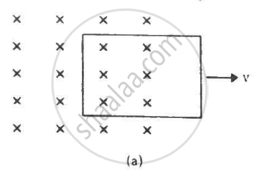
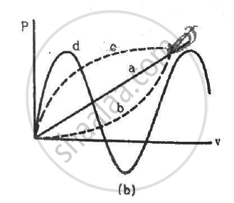
Figure shows a conducting loop being pulled out of a magnetic field with a speed v. Which of the four plots shown in figure (b) may represent the power delivered by the pulling agent as a function of the speed v?
A conducting loop is placed in a uniform magnetic field with its plane perpendicular to the field. An emf is induced in the loop if ___________.
A conducting loop of area 5.0 cm2 is placed in a magnetic field which varies sinusoidally with time as B = B0 sin ωt where B0 = 0.20 T and ω = 300 s−1. The normal to the coil makes an angle of 60° with the field. Find (a) the maximum emf induced in the coil, (b) the emf induced at τ = (π/900)s and (c) the emf induced at t = (π/600) s.
A uniform magnetic field B exists in a cylindrical region of radius 10 cm as shown in figure. A uniform wire of length 80 cm and resistance 4.0 Ω is bent into a square frame and is placed with one side along a diameter of the cylindrical region. If the magnetic field increases at a constant rate of 0.010 T/s, find the current induced in the frame.
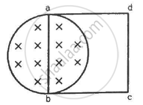
A metallic metre stick moves with a velocity of 2 m s−1 in a direction perpendicular to its length and perpendicular to a uniform magnetic field of magnitude 0.2 T. Find the emf induced between the ends of the stick.
The two rails of a railway track, insulated from each other and from the ground, are connected to a millivoltmeter. What will be the reading of the millivoltmeter when a train travels on the track at a speed of 180 km h−1? The vertical component of earth's magnetic field is 0.2 × 10⁻⁴ T and the rails are separated by 1 m.
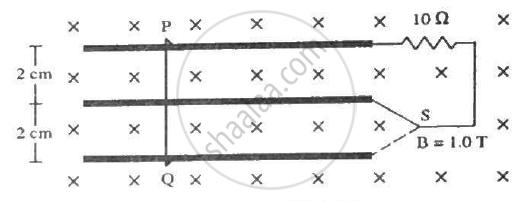
Consider the situation shown in figure. The wire PQ has a negligible resistance and is made to slide on the three rails with a constant speed of 5 cm s−1. Find the current in the 10 Ω resistor when the switch S is thrown to (a) the middle rail (b) the bottom rail.
A rod of length l rotates with a uniform angular velocity ω about its perpendicular bisector. A uniform magnetic field B exists parallel to the axis of rotation. The potential difference between the two ends of the rod is ___________ .
The magnetic field in a region is given by \[\overrightarrow{B} = \overrightarrow{k} \frac{B_0}{L}y\] where L is a fixed length. A conducting rod of length L lies along the Y-axis between the origin and the point (0, L, 0). If the rod moves with a velocity v = v0 \[\overrightarrow{i},\] find the emf induced between the ends of the rod.
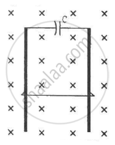
A wire of mass m and length l can slide freely on a pair of smooth, vertical rails (figure). A magnetic field B exists in the region in the direction perpendicular to the plane of the rails. The rails are connected at the top end by a capacitor of capacitance C. Find the acceleration of the wire neglecting any electric resistance.
A uniform magnetic field B exists in a cylindrical region, shown dotted in figure. The magnetic field increases at a constant rate `(dB)/(dt).` Consider a circle of radius r coaxial with the cylindrical region. (a) Find the magnitude of the electric field E at a point on the circumference of the circle. (b) Consider a point P on the side of the square circumscribing the circle. Show that the component of the induced electric field at P along ba is the same as the magnitude found in part (a).

An inductor-coil of inductance 20 mH having resistance 10 Ω is joined to an ideal battery of emf 5.0 V. Find the rate of change of the induced emf at (a) t = 0, (b) t = 10 ms and (c) t = 1.0 s.
An alternating emf of 110 V is applied to a circuit containing a resistance R of 80 Ω and an inductor L in series. The current is found to lag behind the supply voltage by an angle 8 = tan-1 (3/4). Find the :
(i) Inductive reactance
(ii) Impedance of the circuit
(iii) Current flowing in the circuit
(iv) If the inductor has a coefficient of self-inductance of 0.1 H, what is the frequency of the applied emf?
The magnetic potential energy stored in a certain inductor is 25 mJ, when the current in the inductor is 60 mA. This inductor is of inductance ______.
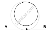
In the given figure current from A to B in the straight wire is decreasing. The direction of induced current in the loop is A ______.
