Advertisements
Advertisements
Question
A parallel-plate capacitor is connected to a battery. A metal sheet of negligible thickness is placed between the plates. The sheet remains parallel to the plates of the capacitor.
Options
The battery will supply more charge.
The capacitance will increase.
The potential difference between the plates will increase.
Equal and opposite charges will appear on the two faces of the metal plate.
Solution
Equal and opposite charges will appear on the two faces of the metal plate.
The capacitance of the capacitor in which a dielectric slab of dielectric constant K, area A and thickness t is inserted between the plates of the capacitor of area A and separated by a distance d is given by `C = (∈_0A)/((d-t)+(t/K))`
Since it is given that the thickness of the sheet is negligible, the above formula reduces to C = `(∈_0A)/d`. In other words, there will not be any change in the electric field, potential or charge.
Only, equal and opposite charges will appear on the two faces of the metal plate because of induction due to the presence of the charges on the plates of the capacitor.
APPEARS IN
RELATED QUESTIONS
Two capacitors of unknown capacitances C1 and C2 are connected first in series and then in parallel across a battery of 100 V. If the energy stored in the two combinations is 0.045 J and 0.25 J respectively, determine the value of C1 and C2. Also calculate the charge on each capacitor in parallel combination.
Three capacitors each of capacitance 9 pF are connected in series.
- What is the total capacitance of the combination?
- What is the potential difference across each capacitor if the combination is connected to a 120 V supply?
Three capacitors of capacitances 2 pF, 3 pF and 4 pF are connected in parallel. Determine the charge on each capacitor if the combination is connected to a 100 V supply.
An electrical technician requires a capacitance of 2 µF in a circuit across a potential difference of 1 kV. A large number of 1 µF capacitors are available to him each of which can withstand a potential difference of not more than 400 V. Suggest a possible arrangement that requires the minimum number of capacitors.
Figure 4 below shows a capacitor C, an inductor L and a resistor R, connected in series
to an a.c. supply of 220 V

Calculate:
1) The resonant frequency of the given CLR circuit.
2) Current flowing through·the circuit.
3) Average power consumed by the circuit.
Suppose a charge +Q1 is given to the positive plate and a charge −Q2 to the negative plate of a capacitor. What is the "charge on the capacitor"?
The plates of a parallel-plate capacitor are given equal positive charges. What will be the potential difference between the plates? What will be the charges on the facing surfaces and on the outer surfaces?
If the capacitors in the previous question are joined in parallel, the capacitance and the breakdown voltage of the combination will be
The separation between the plates of a charged parallel-plate capacitor is increased. Which of the following quantities will change?
(a) Charge on the capacitor
(b) Potential difference across the capacitor
(c) Energy of the capacitor
(d) Energy density between the plates
The plates of a capacitor are 2⋅00 cm apart. An electron-proton pair is released somewhere in the gap between the plates and it is found that the proton reaches the negative plate at the same time as the electron reaches the positive plate. At what distance from the negative plate was the pair released?
A parallel-plate capacitor having plate area 20 cm2 and separation between the plates 1⋅00 mm is connected to a battery of 12⋅0 V. The plates are pulled apart to increase the separation to 2⋅0 mm. (a) Calculate the charge flown through the circuit during the process. (b) How much energy is absorbed by the battery during the process? (c) Calculate the stored energy in the electric field before and after the process. (d) Using the expression for the force between the plates, find the work done by the person pulling the plates apart. (e) Show and justify that no heat is produced during this transfer of charge as the separation is increased.
Three capacitors of capacitance `C_1 = 3muf` , `C_2 = 6muf` , `C_3 = 10muf` , are connected to a 10V battery as shown in figure 3 below :
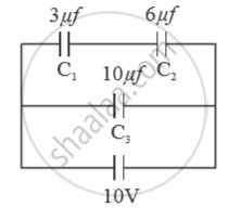
Calculate :
(a) Equivalent capacitance.
(b) Electrostatic potential energy stored in the system
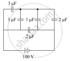
The figure shows a network of five capacitors connected to a 100 V supply. Calculate the total energy stored in the network.
Two parallel plate capacitors X and Y, have the same area of plates and same separation between plates. X has air and Y with dielectric of constant 2, between its plates. They are connected in series to a battery of 12 V. The ratio of electrostatic energy stored in X and Y is ______.
Three capacitors each of 4 µF are to be connected in such a way that the effective capacitance is 6µF. This can be done by connecting them:
Capacitors connected in series have ______
Two charges q1 and q2 are placed at (0, 0, d) and (0, 0, – d) respectively. Find locus of points where the potential a zero.
The total charge on the system of capacitors C1 = 1 µF, C2 = 2 µF, C3 = 4 µF and C4 = 3 µF connected in parallel is ______. (Assume a battery of 20 V is connected to the combination)
