Advertisements
Advertisements
Question
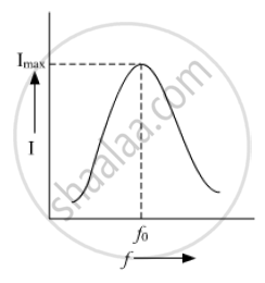
A series LCR circuit is connected to an ac source. Using the phasor diagram, derive the expression for the impedance of the circuit. Plot a graph to show the variation of current with frequency of the source, explaining the nature of its variation.
Solution
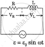
Let an alternating Emf E = E0 sinωt is applied to a series combination of inductor L, capacitor C and resistance R. Since all three of them are connected in series the current through them is same. But the voltage across each element has a different phase relation with current.

The potential difference VL, VC and VR across L, C and R at any instant is given by
VL = IXL, VC = IXC and VR = IR
Where I is the current at that instant.
XL is inductive reactance and
XC is capacitive reactance.
VR is in phase with I. VL leads I by 90° and VC lags behind I by 90°

In the phases diagram,
VL and VC are opposite to each other. If VL > VC then resultant (VL − VC) is represent by OD. OR represent the resultant of VR and (VL − VC). It is equal to the applied Emf E.
`E^2 = V_R^2 + (V_L -V_C)^2`
`E^2 =I^2 +[R^2+(X_L -X_c)^2]`
`or I =E/sqrt (R^2 + (X_2 -X_c)^2)`
The term `sqrt(R^2 +(X_2 - X_c))` is called impedance Z of the LCR circuit.
`Z = sqrt(R^2 +(X_2 -X_c)^2) =sqrt(R^2 +(L omega-1/(comega))^2)`
Emf leads current by a phase angle Φ
`tan phi = (V_L -V_C)/R = (X_L - X_c)/R =(Lomega -1/(comega))/R`
When resonance takes place
`omegaL= 1/(omegac)`
Impedance of circuit becomes equal to R. Current becomes maximum and is equal to `E/R`

`omega_0 = 1/sqrt(LC)`
`f_0 = omega_0/(2pi) = 1/(2pisqrt(LC))`
This is the condition for resonance.
When at resonance f = f0 the current in the circuit is maximum and hence impedance of the circuit is maximum for values of f less than or greater than f0 comparatively small current flames in the circuit.
RELATED QUESTIONS
Define 'quality factor' of resonance in a series LCR circuit. What is its SI unit?
Find the value of t/τ for which the current in an LR circuit builds up to (a) 90%, (b) 99% and (c) 99.9% of the steady-state value.
What will be the potential difference in the circuit when direct current is passed through the circuit?

In series combination of R, L and C with an A.C. source at resonance, if R = 20 ohm, then impedence Z of the combination is ______.
In an LCR series a.c. circuit, the voltage across each of the components, L, C and R is 50V. The voltage across the LC combination will be ______.
A series LCR circuit contains inductance 5 mH, capacitance 2µF and resistance ion. If a frequency A.C. source is varied, what is the frequency at which maximum power is dissipated?
To reduce the resonant frequency in an LCR series circuit with a generator ______.
A series LCR circuit driven by 300 V at a frequency of 50 Hz contains a resistance R = 3 kΩ, an inductor of inductive reactance XL = 250 πΩ, and an unknown capacitor. The value of capacitance to maximize the average power should be ______.
A series LCR circuit containing a resistance of 120 Ω has angular resonance frequency 4 × 10⁵ rad s-1. At resonance the voltage across resistance and inductance are 60 V and 40 V respectively. At what frequency the current in the circuit lags the voltage by 45°. Give answer in ______ × 105 rad s-1.
A series LCR circuit is connected to an ac source. Using the phasor diagram, derive the expression for the impedance of the circuit.
