Advertisements
Advertisements
Question
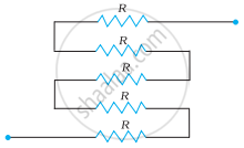
Determine the equivalent resistance of networks shown in Fig.
Solution
It can be observed from the given circuit that five resistors of resistance R each are connected in series.
Hence, equivalent resistance of the circuit = R + R + R + R + R
= 5 R
APPEARS IN
RELATED QUESTIONS
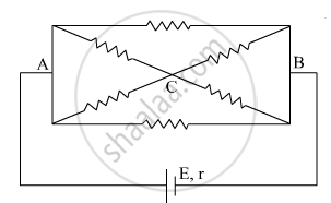
The current is drawn from a cell of emf E and internal resistance r connected to the network of resistors each of resistance r as shown in the figure. Obtain the expression for
- the current draw from the cell and
- the power consumed in the network.
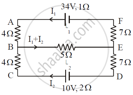
ε1 and ε2 are two batteries having emf of 34V and 10V respectively and internal resistance of 1Ω and 2Ω respectively. They are connected as shown in the figure below. Using Kirchhoff’s Laws of electrical networks, calculate the currents I1 and I2.
Determine the equivalent resistance of networks shown in Fig.

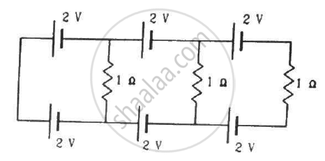
Find the circuit in the three resistors shown in the figure.
Twelve wires, each of equal resistance r, are joined to form a cube, as shown in the figure. Find the equivalent resistance between the diagonally-opposite points a and f.

A capacitor of capacitance 8.0 μF is connected to a battery of emf 6.0 V through a resistance of 24 Ω. Find the current in the circuit (a) just after the connections are made and (b) one time constant after the connections are made.
How the emf of two cells are compared using potentiometer?
Kirchhoff’s second law is a consequence of law of conservation of ______.
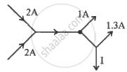
The figure below shows current in a part of electric circuit. The current I is ______.
In a meter bridge the point D is a neutral point (Figure).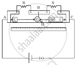
- The meter bridge can have no other neutral point for this set of resistances.
- When the jockey contacts a point on meter wire left of D, current flows to B from the wire.
- When the jockey contacts a point on the meter wire to the right of D, current flows from B to the wire through galvanometer.
- When R is increased, the neutral point shifts to left.
