Advertisements
Advertisements
Question
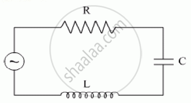
Obtain the resonant frequency and Q-factor of a series LCR circuit with L = 3.0 H, C = 27 µF, and R = 7.4 Ω. It is desired to improve the sharpness of the resonance of the circuit by reducing its ‘full width at half maximum’ by a factor of 2. Suggest a suitable way.
Solution
Inductance, L = 3.0 H
Capacitance, C = 27 μF = 27 × 10−6 F
Resistance, R = 7.4 Ω
At resonance, the angular frequency of the source for the given LCR series circuit is given as:
ωr = `1/sqrt"LC"`
= `1/sqrt(3 xx 27 xx 10^-6)`
= `10^3/9`
= 111.11 rad s−1
Q-factor of the series:
Q = `(ω_"r""L")/"R"`
= `(111.11 xx 3)/7.4`
= 45.0446
To improve the sharpness of the resonance by reducing its ‘full width at half maximum’ by a factor of 2 without changingωr, we need to reduce R to half i.e.,
Resistance = `"R"/2 = 7.4/2` = 3.7 Ω
APPEARS IN
RELATED QUESTIONS
In a series LCR circuit, obtain the condition under which watt-less current flows in the circuit ?
The figure shows a series LCR circuit with L = 10.0 H, C = 40 μF, R = 60 Ω connected to a variable frequency 240 V source, calculate
(i) the angular frequency of the source which drives the circuit at resonance,
(ii) the current at the resonating frequency,
(iii) the rms potential drop across the inductor at resonance.

A solenoid having inductance 4.0 H and resistance 10 Ω is connected to a 4.0 V battery at t = 0. Find (a) the time constant, (b) the time elapsed before the current reaches 0.63 of its steady-state value, (c) the power delivered by the battery at this instant and (d) the power dissipated in Joule heating at this instant.
Derive an expression for the average power dissipated in a series LCR circuit.
Choose the correct answer from given options
The selectivity of a series LCR a.c. circuit is large, when
A series LCR circuit contains inductance 5 mH, capacitance 2µF and resistance ion. If a frequency A.C. source is varied, what is the frequency at which maximum power is dissipated?
The phase diffn b/w the current and voltage at resonance is
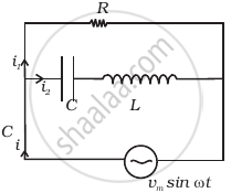
Consider the LCR circuit shown in figure. Find the net current i and the phase of i. Show that i = v/Z`. Find the impedance Z for this circuit.

When an alternating voltage of 220V is applied across device X, a current of 0.25A flows which lags behind the applied voltage in phase by π/2 radian. If the same voltage is applied across another device Y, the same current flows but now it is in phase with the applied voltage.
- Name the devices X and Y.
- Calculate the current flowing in the circuit when the same voltage is applied across the series combination of X and Y.
Draw a labelled graph showing variation of impedance (Z) of a series LCR circuit Vs frequency (f) of the ac supply. Mark the resonant frequency as f0·
