Advertisements
Advertisements
Question
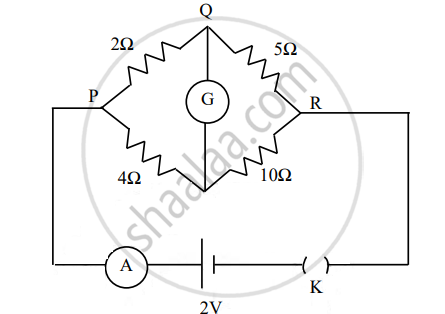
The figure below shows a circuit containing an ammeter A, a galvanometer G and a plug key K. When the key is closed:
Options
both G and A show deflections.
neither G nor A shows deflection.
G shows deflection but A does not.
A shows deflection but G does not.
Solution
A shows deflection but G does not.
APPEARS IN
RELATED QUESTIONS
Draw a labelled diagram of a moving coil galvanometer. Describe briefly its principle and working.
- A circular coil of 30 turns and radius 8.0 cm carrying a current of 6.0 A is suspended vertically in a uniform horizontal magnetic field of magnitude 1.0 T. The field lines make an angle of 60° with the normal of the coil. Calculate the magnitude of the counter torque that must be applied to prevent the coil from turning.
- Would your answer change, if the circular coil in (a) were replaced by a planar coil of some irregular shape that encloses the same area? (All other particulars are also unaltered.)
Explain how moving coil galvanometer is converted into a voltmeter. Derive the necessary formula.
With the help of a neat and labelled diagram, explain the principle and working of a moving coil galvanometer ?
What are the advantages of using soft iron as a core, instead of steel, in the coils of galvanometers?
Why are the pole pieces of a horseshoe magnet in a moving coil galvanometer made cylinder in shape?
A galvanometer coil has a resistance of 12 Ω and the metre shows full scale deflection for a current of 3 mA. How will you convert the metre into a voltmeter of range 0 to 18 V?
The coil of a moving coil galvanometer is wound over a metal frame in order to ______.
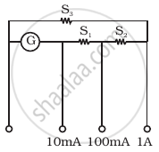
A multirange current meter can be constructed by using a galvanometer circuit as shown in figure. We want a current meter that can measure 10 mA, 100 mA and 1A using a galvanometer of resistance 10 Ω and that prduces maximum deflection for current of 1mA. Find S1, S2 and S3 that have to be used
When a galvanometer is shunted with a 4 Ω resistance, the deflection is reduced to one-fifth. If the galvanometer is further shunted with a 2 Ω wire. The further reduction (find the ratio of decrease in current to the previous current) in the deflection will be (the main current remains the same)
