Advertisements
Advertisements
प्रश्न
Using the phasor diagram, derive the expression for the current flowing in an ideal inductor connected to an a.c. source of voltage, v= vo sin ωt. Hence plot graphs showing the variation of (i) applied voltage and (ii) the current as a function of ωt.
उत्तर

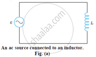
Figure (a) shows an ac source connected to an inductor. Usually, inductors have appreciable resistance in their windings, but we shall assume that this inductor has negligible resistance. Thus, the circuit is a purely inductive ac circuit. Let the voltage across the source be V = Vm sin ωt. Using the Kirchhoff’s loop rule, Σε (t) = 0, and since there is no resistor in the circuit,
`v - L(di)/(dt) = 0` ...(i)
where the second term is the self-induced Faraday emf in the inductor; and L is the self-inductance of the inductor. The negative sign follows from Lenz’s law.
From equation (i) we have
`(di)/(dt) = v/L = v_m/L sin ωt` ...(ii)
Equation (ii) implies that the equation for i(t), the current as a function of time, must be such that its slope di/dt is a sinusoidally varying quantity, with the same phase as the source voltage and an amplitude given by .vm/L
To obtain the current, we integrate di/dt with respect to time:
`int_ (d"i")/(d"t") d"t" = "v"_"m"/"L" int_ sin(wt)dt`
and get
`"i" = -("v"_"m")/(w"L") cos (wt) + cons tan t`
The integration constant has the dimension of current and is time-independent. Since the source has an emf which oscillates symmetrically about zero, the current it sustains also oscillates symmetrically about zero, so that no constant or time-independent component of the current exists. Therefore, the integration constant is zero.
Using
`-cos (wt) = sin(wt - pi/(2)), "we have"`
`"i" - "i"_"m" sin(wt - pi/(2))`
Where `"i"_"m" = ("v"_"m")/(w"L")` is the amplitude of the current.
The quantity ωL is analogous to the resistance and is called inductive reactance, denoted by XL :
`"X"_"L" = w"L"`
The amplitude of the current is, then
`"i"_"m" = ("v"_"m")/("X"_"L")`
The dimension of inductive reactance is the same as that of resistance and its SI unit is ohm (Ω). The inductive reactance limits the current in a purely inductive circuit in the same way as the resistance limits the current in a purely resistive circuit. The inductive reactance is directly proportional to the inductance and to the frequency of the current.

Fig. (b) A Phasor diagram for the circuit in Fig.(a) Fog. (c) Graph of v and i versus wt.
APPEARS IN
संबंधित प्रश्न
Why does current in a steady state not flow in a capacitor connected across a battery? However momentary current does flow during charging or discharging of the capacitor. Explain.
A coil of resistance 40 Ω is connected across a 4.0 V battery. 0.10 s after the battery is connected, the current in the coil is 63 mA. Find the inductance of the coil.
The current in a discharging LR circuit without the battery drops from 2.0 A to 1.0 A in 0.10 s. (a) Find the time constant of the circuit. (b) If the inductance of the circuit 4.0 H, what is its resistance?
A constant current exists in an inductor-coil connected to a battery. The coil is short-circuited and the battery is removed. Show that the charge flown through the coil after the short-circuiting is the same as that which flows in one time constant before the short-circuiting.
Draw a labelled graph showing a variation of impedance of a series LCR circuit with frequency of the a.c. supply.
Answer the following question.
What is the phase difference between the voltages across the inductor and the capacitor at resonance in the LCR circuit?
Keeping the source frequency equal to the resonating frequency of the series LCR circuit, if the three elements, L, C and R are arranged in parallel, show that the total current in the parallel LCR circuit is minimum at this frequency. Obtain the current rms value in each branch of the circuit for the elements and source specified for this frequency.
If the rms current in a 50 Hz ac circuit is 5 A, the value of the current 1/300 seconds after its value becomes zero is ______.
As the frequency of an ac circuit increases, the current first increases and then decreases. What combination of circuit elements is most likely to comprise the circuit?
- Inductor and capacitor.
- Resistor and inductor.
- Resistor and capacitor.
- Resistor, inductor and capacitor.
