Advertisements
Advertisements
Question
Using the phasor diagram, derive the expression for the current flowing in an ideal inductor connected to an a.c. source of voltage, v= vo sin ωt. Hence plot graphs showing the variation of (i) applied voltage and (ii) the current as a function of ωt.
Solution

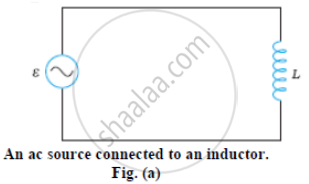
Figure (a) shows an ac source connected to an inductor. Usually, inductors have appreciable resistance in their windings, but we shall assume that this inductor has negligible resistance. Thus, the circuit is a purely inductive ac circuit. Let the voltage across the source be V = Vm sin ωt. Using the Kirchhoff’s loop rule, Σε (t) = 0, and since there is no resistor in the circuit,
`v - L(di)/(dt) = 0` ...(i)
where the second term is the self-induced Faraday emf in the inductor; and L is the self-inductance of the inductor. The negative sign follows from Lenz’s law.
From equation (i) we have
`(di)/(dt) = v/L = v_m/L sin ωt` ...(ii)
Equation (ii) implies that the equation for i(t), the current as a function of time, must be such that its slope di/dt is a sinusoidally varying quantity, with the same phase as the source voltage and an amplitude given by .vm/L
To obtain the current, we integrate di/dt with respect to time:
`int_ (d"i")/(d"t") d"t" = "v"_"m"/"L" int_ sin(wt)dt`
and get
`"i" = -("v"_"m")/(w"L") cos (wt) + cons tan t`
The integration constant has the dimension of current and is time-independent. Since the source has an emf which oscillates symmetrically about zero, the current it sustains also oscillates symmetrically about zero, so that no constant or time-independent component of the current exists. Therefore, the integration constant is zero.
Using
`-cos (wt) = sin(wt - pi/(2)), "we have"`
`"i" - "i"_"m" sin(wt - pi/(2))`
Where `"i"_"m" = ("v"_"m")/(w"L")` is the amplitude of the current.
The quantity ωL is analogous to the resistance and is called inductive reactance, denoted by XL :
`"X"_"L" = w"L"`
The amplitude of the current is, then
`"i"_"m" = ("v"_"m")/("X"_"L")`
The dimension of inductive reactance is the same as that of resistance and its SI unit is ohm (Ω). The inductive reactance limits the current in a purely inductive circuit in the same way as the resistance limits the current in a purely resistive circuit. The inductive reactance is directly proportional to the inductance and to the frequency of the current.

Fig. (b) A Phasor diagram for the circuit in Fig.(a) Fog. (c) Graph of v and i versus wt.
APPEARS IN
RELATED QUESTIONS
In a series LCR circuit, VL = VC ≠ VR. What is the value of power factor?
A source of ac voltage v = v0 sin ωt, is connected across a pure inductor of inductance L. Derive the expressions for the instantaneous current in the circuit. Show that average power dissipated in the circuit is zero.
In a series LCR circuit, obtain the condition under which the impedance of the circuit is minimum ?
The magnetic field at a point inside a 2.0 mH inductor-coil becomes 0.80 of its maximum value in 20 µs when the inductor is joined to a battery. Find the resistance of the circuit.
The current in a discharging LR circuit without the battery drops from 2.0 A to 1.0 A in 0.10 s. (a) Find the time constant of the circuit. (b) If the inductance of the circuit 4.0 H, what is its resistance?
When an alternating voltage of 220V is applied across device X, a current of 0.25A flows which lags behind the applied voltage in phase by π/2 radian. If the same voltage is applied across another device Y, the same current flows but now it is in phase with the applied voltage.
- Name the devices X and Y.
- Calculate the current flowing in the circuit when the same voltage is applied across the series combination of X and Y.
A series LCR circuit is connected to an ac source. Using the phasor diagram, derive the expression for the impedance of the circuit.
Select the most appropriate option with regard to resonance in a series LCR circuit.
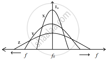
Three students, X, Y and Z performed an experiment for studying the variation of a.c. with frequency in a series LCR circuit and obtained the graphs as shown below. They all used
- an AC source of the same emf and
- inductance of the same value.

- Who used minimum resistance?
- In which case will the quality Q factor be maximum?
- What did the students conclude about the nature of impedance at resonant frequency (f0)?
- An ideal capacitor is connected across 220V, 50Hz, and 220V, 100Hz supplies. Find the ratio of current flowing through it in the two cases.
