Advertisements
Advertisements
प्रश्न
Draw a schematic sketch of an ac generator describing its basic elements. State briefly its working principle. Show a plot of variation of
(i) Magnetic flux and
(ii) Alternating emf versus time generated by a loop of wire rotating in a magnetic field.
उत्तर
Principle − Based on the phenomenon of electromagnetic induction.
Construction:

Main parts of an ac generator:
Armature − The rectangular coil ABCD
Filed Magnets − Two pole pieces of a strong electromagnet
Slip Rings − The ends of the coil ABCD are connected to two hollow metallic rings R1 and R2.
Brushes − B1 and B2 are two flexible metal plates or carbon rods. They are fixed and are kept in tight contact with R1 and R2, respectively.
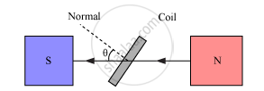
Working − As the armature coil is rotated in the magnetic field, angle θ between the field and the normal to the coil changes continuously. Therefore, magnetic flux linked with the coil changes and an emf is induced in the coil. According to Fleming’s right hand rule, current is induced from A to B in AB and from C to D in CD. In the external circuit, current flows from B2 to B1.
To calculate the magnitude of emf induced:
Suppose A → Area of each turn of the coil
N → Number of turns in the coil
`vecB`→ Strength of the magnetic field
θ → Angle which normal to the coil makes with `vecB` at any instant t
∴ Magnetic flux linked with the coil in this position is given by,
`phi=N(vecB.vecA)=NBAcostheta=NBAcos `
Where, ‘ω’ is angular velocity of the coil
Graph between magnetic flux and time, according to equation (i), is shown below:

As the coil rotates, angle θ changes. Therefore, magnetic flux Φ linked with the coil changes and an emf is induced in the coil. At this instant t, if e is the emf induced in the coil, then
`e=(dtheta)/dt=-d/dt(NABcos`
`=-NABd/dt(cos `
=-NAB(-sin ωt)ω
∴ e = NAB ω sin ωt
The graph between alternating emf versus time is shown below:

APPEARS IN
संबंधित प्रश्न
A square loop MNOP of side 20 cm is placed horizontally in a uniform magnetic field acting vertically downwards as shown in the figure. The loop is pulled with a constant velocity of 20 cm s−1 till it goes out of the field.
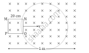
(i) Depict the direction of the induced current in the loop as it goes out of the field. For how long would the current in the loop persist?
(ii) Plot a graph showing the variation of magnetic flux and induced emf as a function of time.
The current flowing through an inductor of self inductance L is continuously increasing. Plot a graph showing the variation of
Magnetic flux versus the current
A pair of adjacent coils has a mutual inductance of 1.5 H. If the current in one coil changes from 0 to 20 A in 0.5 s, what is the change of flux linkage with the other coil?
A rectangular coil having 60 turns and area of 0.4m2 is held at right angles to a uniform magnetic field of flux density 5 × 10⁻⁵T. Calculate the magnetic flux passing through it.
How does the mutual inductance of a pair of coils change when
(i) distance between the coils is increased and
(ii) number of turns in the coils is increased?
A metallic loop is placed in a nonuniform magnetic field. Will an emf be induced in the loop?
An inductor is connected to a battery through a switch. Explain why the emf induced in the inductor is much larger when the switch is opened as compared to the emf induced when the switch is closed.
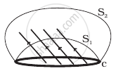
Consider a closed loop C in a magnetic field (Figure). The flux passing through the loop is defined by choosing a surface whose edge coincides with the loop and using the formula φ = B1.dA1 + B2.dA2 +... Now if we chose two different surfaces S1 and S2 having C as their edge, would we get the same answer for flux. Jusity your answer.
A circular coil has radius ‘r', number of turns ‘N’ and carries a current ‘I’. Magnetic flux density ‘B’ at its centre is ______.
