Advertisements
Advertisements
Question
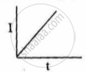
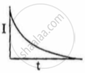
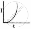
A solenoid L and a resistor R are connected in series to a battery, through a switch. When the switch is put on, current I flowing through it varies with time t as shown in which of the graphs given below:
Options
Solution
A solenoid L and a resistor R are connected in series to a battery, through a switch. When the switch is put on, current I flowing through it varies with time t as shown in which of the graphs given below:

APPEARS IN
RELATED QUESTIONS
Three resistors 1 Ω, 2 Ω, and 3 Ω are combined in series. What is the total resistance of the combination?
Which of the following quantities does not change when a resistor connected to a battery is heated due to the current?
If the reading of the ammeter, A1 in the following figure is 2.4 A, what will be the readings of ammeters A2 and A3? Neglect the resistances of the ammeters.

A bulb is made using two filaments. A switch selects whether the filaments are used individually or in parallel. When used with a 15 V battery, the bulb can be operated at 5 W, 10 W or 15 W. What should be the resistances of the filaments?
The emf ε and the internal resistance r of the battery, shown in the figure, are 4.3 V and 1.0 Ω respectively. The external resistance R is 50 Ω. The resistances of the ammeter and voltmeter are 2.0 Ω and 200 Ω respectively. (a) Find the readings of the two meters. (b) The switch is thrown to the other side. What will be the readings of the two meters now?

Two resistors R1= 60 Ω and R2 = 90Ω are connected in parallel. If electric power consumed by the resistor R1 is15 W, calculate the power consumed by the resistor R2.
If two resistors of resistances R1 = (4 ± 0.5) Ω and R2 = (16 ± 0.5) Ω are connected in series. The eqivalent resistance with the limits of percentage error is ______.
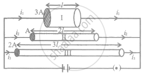
The figure shows three conductors I, II and III of same material, different lengths l, 2l and 3l and of different areas of cross-sections 3A, A and 2A respectively. Arrange them in the increasing order of current drawn from the battery.

The effective resistance of a parallel connection that consists of four wires of equal length, equal area of cross-section and the same material is 0.25 Ω. What will be the effective resistance if they are connected in series?
Let there be n resistors R1............Rn with Rmax = max (R1......... Rn) and Rmin = min {R1..... Rn}. Show that when they are connected in parallel, the resultant resistance RP < R min and when they are connected in series, the resultant resistance RS > Rmax. Interpret the result physically.


