Advertisements
Advertisements
Question
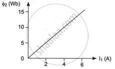
Two coils C1 and C2 are placed close to each other. The magnetic flux Φ2 linked with coil C2 varies with the current I1 flowing in coil C1 as shown in the figure. Find

- The mutual inductance of the arrangement, and
- The rate of change of current `((dI_1)/(dt))` will induce an emf of 100V in coil C2.
Solution
- Φ2 = magnetic flux linked with coil C2.
I1 = current passes in coil C1.
Lets no. of turns in coil C1 be N1.
No. of turns in coil C2 be N2.
According to Faraday's law,
`E_"ind" = (dphi)/(dt)`
`E_{21} = -N_2(dphi_2)/(dt)`
`E_21 = -N_2d/dt(vecB . vecA)`
`N_2phi_2 prop I_1`
`N_2phi_2 = M_21I_1`
M21 is called mutual inductance.
`M_21 = (N_2phi_2)/I_1` - Induced emf (E) = `-L(dI)/(dt)`
`(dI)/(dt) = E/(-L)`
`(dI_1)/(dt) = -100(1/L)`
Here, L is the inductance of the coil C2.
APPEARS IN
RELATED QUESTIONS
A circular coil of radius 8.0 cm and 20 turns is rotated about its vertical diameter with an angular speed of 50 rad s−1 in a uniform horizontal magnetic field of magnitude 3.0 × 10⁻² T. Obtain the maximum and average emf induced in the coil. If the coil forms a closed loop of resistance 10 Ω, calculate the maximum value of current in the coil. Calculate the average power loss due to Joule heating. Where does this power come from?
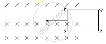
The closed loop (PQRS) of wire is moved into a uniform magnetic field at right angles to the plane of the paper as shown in the figure, Predict the direction of the induced current in the loop.

A .0.5m long solenoid of 10 turns/cm has area of cross-section 1cm2 . Calculate the voltage induced across its ends if the current in the solenoid is changed from 1A to 2A in 0.1s.
According to Faraday’s law of electromagnetic induction ______.
A (current vs time) graph of the current passing through a solenoid is shown in figure. For which time is the back electromotive force (u) a maximum. If the back emf at t = 3s is e, find the back emf at t = 7s, 15s and 40s. OA, AB and BC are straight line segments.

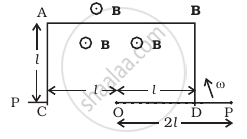
ODBAC is a fixed rectangular conductor of negilible resistance (CO is not connnected) and OP is a conductor which rotates clockwise with an angular velocity ω (Figure). The entire system is in a uniform magnetic field B whose direction is along the normal to the surface of the rectangular conductor ABDC. The conductor OP is in electric contact with ABDC. The rotating conductor has a resistance of λ per unit length. Find the current in the rotating conductor, as it rotates by 180°.

A magnetic field B is confined to a region r ≤ a and points out of the paper (the z-axis), r = 0 being the centre of the circular region. A charged ring (charge = Q) of radius b, b > a and mass m lies in the x-y plane with its centre at the origin. The ring is free to rotate and is at rest. The magnetic field is brought to zero in time ∆t. Find the angular velocity ω of the ring after the field vanishes.
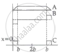
The arm PQ of a rectangular conductor is moving from x = 0 to x = 2b outwards and then inwards from x = 2b to x = 0 as shown in the figure. A uniform magnetic field perpendicular to the plane is acting from x = 0 to x = b. Identify the graph showing the variation of different quantities with distance.


A coil of effective area 4 m2 is placed at right angles to the magnetic induction B. The e.m.f. of 0.32 V is induced in the coil. When the field is reduced to 20% of its initial value in 0.5 sec. Find B (in wb/m2).
A square-shaped coil of side 10 cm, having 100 turns is placed perpendicular to a magnetic field which is increasing at 1 T/s. The induced emf in the coil is ______.
