Advertisements
Advertisements
Question
Which of the following combinations should be selected for better tuning of an LCR circuit used for communication?
Options
R = 20 Ω, L = 1.5 H, C = 35µF.
R = 25 Ω, L = 2.5 H, C = 45µF.
R = 15 Ω, L = 3.5 H, C = 30µF.
R = 25 Ω, L = 1.5 H, C = 45µF.
Solution
R = 15 Ω, L = 3.5 H, C = 30µF.
Explanation:
Quality factor (Q-factor) of the series resonant circuit:
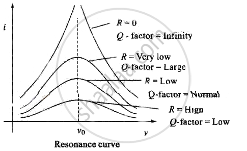
(i) The characteristic of a series resonant circuit is determined by the quality factor (Q-factor) of the circuit.
(ii) It defines sharpness if i - v curve at resonance when Q-factor is large, the sharpness of resonance curve is more and vice-versa.
(iii) Q-factor is also defined as follows:
Q-factor = `2pi xx "Max energy stored"/"Energy dissipation"`
= `(2pi)/T xx "Max energy stored"/"Mean power dissipated"`
= `"Resonant frequency"/"Bandwidth" = ω_0/(Δω)`
(iv) Q-factor = `V_L/V_R` or `V_C/V_R = (ω_0L)/R` or `1/(ω_0CR)`
⇒ Q-factor = `1/R sqrt(L/C)`
For better tuning of an L-C-R circuit used for communication, quality factor of the circuit must be as high as possible.
We know quality factor should be high for better tuning.
Quality factor (Q) of an L-C-R circuit is `Q = 1/R sqrt(L/C)`
Where R is the resistance, L is the inductance and C is the capacitance of the circuit.
For high Q factor R should be low, L should be high and C should be low.
Important point: Be careful while writing formula for quality factor, this formula we used in this case is only for series L-C-R circuit.
APPEARS IN
RELATED QUESTIONS
A voltage V = V0 sin ωt is applied to a series LCR circuit. Derive the expression for the average power dissipated over a cycle. Under what condition (i) no power is dissipated even though the current flows through the circuit, (ii) maximum power is dissipated in the circuit?
A coil of resistance 40 Ω is connected across a 4.0 V battery. 0.10 s after the battery is connected, the current in the coil is 63 mA. Find the inductance of the coil.
An LR circuit with emf ε is connected at t = 0. (a) Find the charge Q which flows through the battery during 0 to t. (b) Calculate the work done by the battery during this period. (c) Find the heat developed during this period. (d) Find the magnetic field energy stored in the circuit at time t. (e) Verify that the results in the three parts above are consistent with energy conservation.
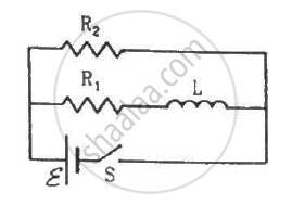
Consider the circuit shown in figure. (a) Find the current through the battery a long time after the switch S is closed. (b) Suppose the switch is again opened at t = 0. What is the time constant of the discharging circuit? (c) Find the current through the inductor after one time constant.
Use the expression for Lorentz force acting on the charge carriers of a conductor to obtain the expression for the induced emf across the conductor of length l moving with velocity v through a magnetic field B acting perpendicular to its length.
Derive an expression for the average power dissipated in a series LCR circuit.
The phase diffn b/w the current and voltage at resonance is
A series LCR circuit containing 5.0 H inductor, 80 µF capacitor and 40 Ω resistor is connected to 230 V variable frequency ac source. The angular frequencies of the source at which power transferred to the circuit is half the power at the resonant angular frequency are likely to be ______.
To reduce the resonant frequency in an LCR series circuit with a generator ______.
