Advertisements
Advertisements
Question
What happens when a forward bias is applied to a p-n junction?
Solution
In forward biasing, the applied voltage mostly drops across the depletion region, and the voltage drop across the p-side and n-side of the junction is negligible. The direction of the applied voltage (V) is opposite to the built-in potential Vo. As a result, the depletion layer width decreases and the barrier height is reduced. The effective barrier height under forward bias is (Vo − V).
APPEARS IN
RELATED QUESTIONS
When a forward bias is applied to a p-n junction, it ______.
Draw its I – V characteristics of photodiode
In the following diagram, is the junction diode forward biased or reverse biased ?
The dynamic plate resistance of a triode value is 10 kΩ. Find the change in the plate current if the plate voltage is changed from 200 V to 220 V.
Answer the following question.
Why photodiodes are required to operate in reverse bias? Explain.
Depletion layer in p - n junction diode consists of
When we apply reverse biased to a junction diode, it
The expected energy of the electron at absolute zero is called:-
In the circuit shown in figure, if the diode forward voltage drop is 0.3 V, the voltage difference between A and B is ______.

Consider a box with three terminals on top of it as shown in figure (a):
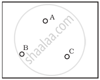 (a) |
Three components namely, two germanium diodes and one resistor are connected across these three terminals in some arrangement. A student performs an experiment in which any two of these three terminals are connected in the circuit shown in figure (b).
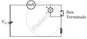 (b) |
The student obtains graphs of current-voltage characteristics for unknown combination of components between the two terminals connected in the circuit. The graphs are
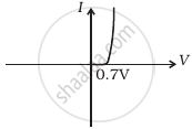
(i) when A is positive and B is negative
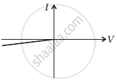 (c) |
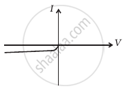
(ii) when A is negative and B is positive
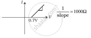 (d) |
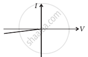
(iii) When B is negative and C is positive
|
(e) |
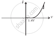
(iv) When B is positive and C is negative
 (f) |
(v) When A is positive and C is negative
 (g) |
(vi) When A is negative and C is positive
 (h) |
From these graphs of current-voltage characteristics shown in figure (c) to (h), determine the arrangement of components between A, B and C.
