Advertisements
Advertisements
Question
A battery of emf 10 V and internal resistance 3 Ω is connected to a resistor. If the current in the circuit is 0.5 A, what is the resistance of the resistor? What is the terminal voltage of the battery when the circuit is closed?
Solution
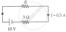
Emf of the battery, E = 10 V
The internal resistance of the battery, r = 3 Ω
Current in the circuit, I = 0.5 A
Resistance of the resistor = R
The relation for current using Ohm’s law is,
I = `"E"/("R" + "r")`
R + r = `"E"/"I"`
= `10/0.5`
= 20 Ω
∴ R = 20 − 3 = 17 Ω
Terminal voltage of the resistor = V
According to Ohm’s law,
V = IR
= 0.5 × 17
= 8.5 V
Therefore, the resistance of the resistor is 17 Ω, and the terminal voltage is 8.5 V.
APPEARS IN
RELATED QUESTIONS
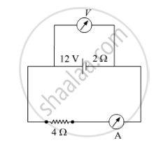
A battery of emf 12 V and internal resistance 2 Ω is connected to a 4 Ω resistor as shown in the figure.
(a) Show that a voltmeter when placed across the cell and across the resistor, in turn, gives the same reading.
(b) To record the voltage and the current in the circuit, why is voltmeter placed in parallel and ammeter in series in the circuit?
Two identical cells of emf 1.5 V each joined in parallel, supply energy to an external circuit consisting of two resistances of 7 Ω each joined in parallel. A very high resistance voltmeter reads the terminal voltage of cells to be 1.4 V. Calculate the internal resistance of each cell.
A cell of emf 'E' and internal resistance 'r' is connected across a variable load resistor R. Draw the plots of the terminal voltage V versus (i) R and (ii) the current I.
It is found that when R = 4 Ω, the current is 1 A and when R is increased to 9 Ω, the current reduces to 0.5 A. Find the values of the emf E and internal resistance r.
A cell of emf 'E' and internal resistance 'r' is connected across a variable resistor 'R'. Plot a graph showing variation of terminal voltage 'V' of the cell versus the current 'I'. Using the plot, show how the emf of the cell and its internal resistance can be determined.
A storage battery of emf 8.0 V and internal resistance 0.5 Ω is being charged by a 120 V dc supply using a series resistor of 15.5 Ω. What is the terminal voltage of the battery during charging? What is the purpose of having a series resistor in the charging circuit?
A secondary cell after long use has an emf of 1.9 V and a large internal resistance of 380 Ω. What maximum current can be drawn from the cell? Could the cell drive the starting motor of a car?
In a potentiometer arrangement for determining the emf of a cell, the balance point of the cell in open circuit is 350 cm. When a resistance of 9 Ω is used in the external circuit of the cell, the balance point shifts to 300 cm. Determine the internal resistance of the cell.
The equivalent resistance between points. a and f of the network shown in Figure 2 is :
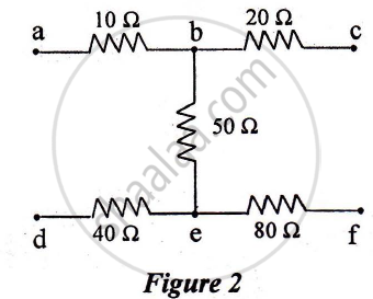
a) 24 Ω
b) 110 Ω
c) 140 Ω
d) 200 Ω
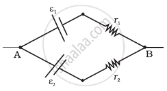
Two cells of emf E1, E2 and internal resistance r1 and r2 respectively are connected in parallel as shown in the figure.

Deduce the expressions for
(1) the equivalent e.m.f of the combination
(2) the equivalent resistance of the combination, and
(3) the potential difference between the point A and B.
The temperatures of the junctions of a bismuth-silver thermocouple are maintained at 0°C and 0.001°C. Find the thermo-emf (Seebeck emf) developed. For bismuth-silver, a = − 46 × 10−6 V°C−1 and b = −0.48 × 10⁻⁶ V°C−2.
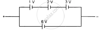
Find the emf of the battery shown in the figure:
Answer the following question.
What is the end error in a meter bridge? How is it overcome? The resistances in the two arms of the metre bridge are R = Ω and S respectively. When the resistance S is shunted with equal resistance, the new balance length found to be 1.5 l1, where l2 is the initial balancing length. calculate the value of s.

Answer the following question.
A cell of emf E and internal resistance r is connected across a variable resistor R. Plot the shape of graphs showing a variation of terminal voltage V with (i) R and (ii) circuit current I.
A conductor of length 'l' is rotated about one of its ends at a constant angular speed 'ω' in a plane perpendicular to a uniform magnetic field B. Plot graphs to show variations of the emf induced across the ends of the conductor with (i) angular speed ω and (ii) length of the conductor l.
Five cells each of emf E and internal resistance r send the same amount of current through an external resistance R whether the cells are connected in parallel or in series. Then the ratio `("R"/"r")` is:
Two batteries of emf ε1 and ε2 (ε2 > ε1) and internal resistances r1 and r2 respectively are connected in parallel as shown in figure.
Three cells, each of emf E but internal resistances 2r, 3r and 6r are connected in parallel across a resistor R.
Obtain expressions for (i) current flowing in the circuit, and (ii) the terminal potential differences across the equivalent cell.
An ac generator generates an emf which is given by e = 311 sin (240 πt) V. Calculate:
- frequency of the emf.
- r.m.s. value of the emf.
Study the two circuits shown in the figure below. The cells in the two circuits are identical to each other. The resistance of the load resistor R is the same in both circuits.
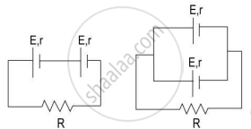
If the same current flows through the resistor R in both circuits, calculate the internal resistance of each cell in terms of the resistance of resistor R. Show your calculations.
