Advertisements
Advertisements
Question
An inductor-coil of inductance 20 mH having resistance 10 Ω is joined to an ideal battery of emf 5.0 V. Find the rate of change of the induced emf at (a) t = 0, (b) t = 10 ms and (c) t = 1.0 s.
Solution
Given:-
Self-inductance, L = 20 mH
Emf of the battery, e = 5.0 V
Resistance, R = 10 Ω
Now,
Time constant of the coil:-
\[\tau = \frac{L}{R} = \frac{20 \times {10}^{- 3}}{10}=2\times10^{-3} s\]
Steady-state current:-
\[i_0 = \frac{e}{R} = \frac{5}{10} = 0 . 5\]
The current in the LR circuit at time t is given by
i = i0(1 − e−t/τ)
⇒ i = i0 − i0e−t/τ
On differentiating both sides, we get
\[\frac{di}{dt} = \frac{i_0}{\tau} e^{- t/\tau}\]
The rate of change of the induced emf is given by
\[R\frac{di}{dt} = R\frac{i_0}{\tau} \times e^{- t/\tau}\]
(a) At time t = 0 s, the rate of change of the induced emf is given by
\[R\frac{di}{dt} = R\frac{i_0}{\tau}\]
\[ = 10 \times \frac{0 . 5}{2 \times {10}^{- 3}}\]
\[ = 2 . 5 \times {10}^3 V/s\]
(b) At time t = 10 ms, the rate of change of the induced emf is given by
\[R\frac{di}{dt} = R\frac{i_0}{\tau} \times e^{- t/\tau}\]
Now,
For t = 10 ms = 10 × 10−3 s = 10−2 s,
\[\frac{dE}{dt} = 10 \times \frac{5}{10} \times \frac{1}{2 \times {10}^{- 3}} \times e^{- 0 . 01/(2\times 10^{- 3})} \]
= 16.844 = 17 V/s
(c) At time t = 1 s, the rate of change of the induced emf is given by
\[\frac{dE}{dt} = \frac{Rdi}{dt} = R\frac{i_0}{\tau} \times e^{- t/\tau}\]
\[= 10 \times \frac{5 \times {10}^{- 1}}{2 \times {10}^{- 3}} \times e^{- 1/(2\times 10^{- 3})}\]
= 0.00 V/s
APPEARS IN
RELATED QUESTIONS
Two cells of emf E1 and E2 and internal resistances r1 and r2 are connected in parallel. Derive the expression for the (i) emf and (ii) internal resistance of a single equivalent cell which can replace this combination.
A metallic rod of length ‘l’ is rotated with a frequency v with one end hinged at the centre and the other end at the circumference of a circular metallic ring of radius r, about an axis passing through the centre and perpendicular to the plane of the ring. A constant uniform magnetic field B parallel to the axis is present everywhere. Using Lorentz force, explain how emf is induced between the centre and the metallic ring and hence obtained the expression for it.
Consider the situation shown in figure. The wire AB is slid on the fixed rails with a constant velocity. If the wire AB is replaced by a semicircular wire, the magnitude of the induced current will _____________ .

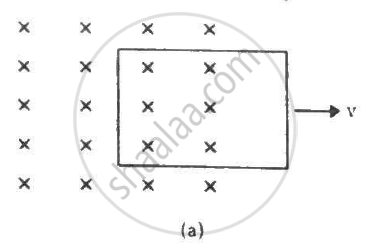
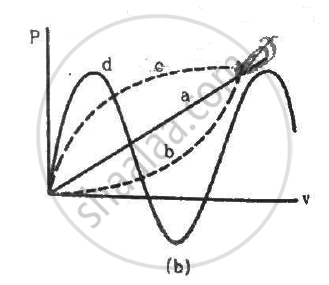
Figure shows a conducting loop being pulled out of a magnetic field with a speed v. Which of the four plots shown in figure (b) may represent the power delivered by the pulling agent as a function of the speed v?
A small, conducting circular loop is placed inside a long solenoid carrying a current. The plane of the loop contains the axis of the solenoid. If the current in the solenoid is varied, the current induced in the loop is __________________ .
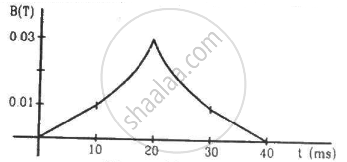
(a) The magnetic field in a region varies as shown in figure. Calculate the average induced emf in a conducting loop of area 2.0 × 10⁻³ m2 placed perpendicular to the field in each of the 10 ms intervals shown. (b) In which intervals is the emf not constant? Neglect the behaviour near the ends of 10 ms intervals.
A conducting loop of area 5.0 cm2 is placed in a magnetic field which varies sinusoidally with time as B = B0 sin ωt where B0 = 0.20 T and ω = 300 s−1. The normal to the coil makes an angle of 60° with the field. Find (a) the maximum emf induced in the coil, (b) the emf induced at τ = (π/900)s and (c) the emf induced at t = (π/600) s.
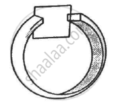
Figure shows a conducting square loop placed parallel to the pole-faces of a ring magnet. The pole-faces have an area of 1 cm2 each and the field between the poles is 0.10 T. The wires making the loop are all outside the magnetic field. If the magnet is removed in 1.0 s, what is the average emf induced in the loop?
A wire-loop confined in a plane is rotated in its own plane with some angular velocity. A uniform magnetic field exists in the region. Find the emf induced in the loop.
A uniform magnetic field B exists in a cylindrical region of radius 10 cm as shown in figure. A uniform wire of length 80 cm and resistance 4.0 Ω is bent into a square frame and is placed with one side along a diameter of the cylindrical region. If the magnetic field increases at a constant rate of 0.010 T/s, find the current induced in the frame.
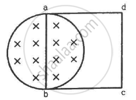
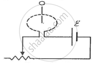
Figure shows a circular coil of N turns and radius a, connected to a battery of emf εthrough a rheostat. The rheostat has a total length L and resistance R. the resistance of the coil is r. A small circular loop of radius a' and resistance r' is placed coaxially with the coil. The centre of the loop is at a distance x from the centre of the coil. In the beginning, the sliding contact of the rheostat is at the left end and then onwards it is moved towards right at a constant speed v. Find the emf induced in the small circular loop at the instant (a) the contact begins to slide and (b) it has slid through half the length of the rheostat.
A wire of length 10 cm translates in a direction making an angle of 60° with its length. The plane of motion is perpendicular to a uniform magnetic field of 1.0 T that exists in the space. Find the emf induced between the ends of the rod if the speed of translation is 20 cm s−1.
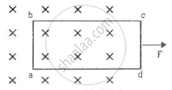
A rectangular frame of wire abcd has dimensions 32 cm × 8.0 cm and a total resistance of 2.0 Ω. It is pulled out of a magnetic field B = 0.020 T by applying a force of 3.2 × 10⁻⁵N (see the following figure). It is found that the frame moves with constant speed. Find (a) this constant speed, (b) the emf induced in the loop, (c) the potential difference between the points aand b and (d) the potential difference between the points c and d.
A conducting wire ab of length l, resistance r and mass m starts sliding at t = 0 down a smooth, vertical, thick pair of connected rails as shown in figure. A uniform magnetic field B exists in the space in a direction perpendicular to the plane of the rails. (a) Write the induced emf in the loop at an instant t when the speed of the wire is v. (b) What would be the magnitude and direction of the induced current in the wire? (c) Find the downward acceleration of the wire at this instant. (d) After sufficient time, the wire starts moving with a constant velocity. Find this velocity vm. (e) Find the velocity of the wire as a function of time. (f) Find the displacement of the wire as a function of time. (g) Show that the rate of heat developed in the wire is equal to the rate at which the gravitational potential energy is decreased after steady state is reached.
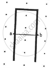
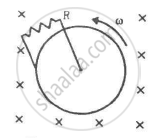
Figure shows a conducting disc rotating about its axis in a perpendicular magnetic field B. A resistor of resistance R is connected between the centre and the rim. Calculate the current in the resistor. Does it enter the disc or leave it at the centre? The radius of the disc is 5.0 cm, angular speed ω = 10 rad/s, B = 0.40 T and R = 10 Ω.
An alternating emf of 110 V is applied to a circuit containing a resistance R of 80 Ω and an inductor L in series. The current is found to lag behind the supply voltage by an angle 8 = tan-1 (3/4). Find the :
(i) Inductive reactance
(ii) Impedance of the circuit
(iii) Current flowing in the circuit
(iv) If the inductor has a coefficient of self-inductance of 0.1 H, what is the frequency of the applied emf?
Plot a graph showing variation of induced e.m.f. with the rate of change of current flowing through a coil.
The magnetic potential energy stored in a certain inductor is 25 mJ, when the current in the inductor is 60 mA. This inductor is of inductance ______.
When the rate of change oic current is unity, the induced emf is equal to ______.
