Advertisements
Advertisements
Question
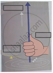
Write Fleming’s right hand thumb rule with the help of diagram.
Solution

If a current-carrying straight conductor is held in our right hand such that the thumb points towards the direction of the current, then the curled fingers around the conductor will give the direction of the magnetic field.
APPEARS IN
RELATED QUESTIONS
A solenoid of length 1.5 m and 4 cm in diameter possesses 10 turns per metre. A current of 5 A is flowing through it. The magnetic induction at a point inside the solenoid along the axis is ............................. .
(μ0 = 4π × 10-7 Wb/Am)
- π × 10-5 T
- 2π × 10-5 T
- 3π × 10-5 T
- 4π × 10-5 T
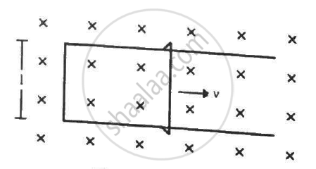
A rectangular wire loop of sides 8 cm and 2 cm with a small cut is moving out of a region of uniform magnetic field of magnitude 0.3 T directed normal to the loop. What is the emf developed across the cut if the velocity of the loop is 1 cm s−1 in a direction normal to the
- longer side,
- shorter side of the loop?
For how long does the induced voltage last in each case?
The magnetic flux through a loop is varying according to a relation `phi = 6t^2 + 7t + 1` where `phi` is in milliweber and t is in second. What is the e.m.f. induced in the loop at t = 2 second?
What is electromagnetic induction?
A circular coil of cross-sectional area 200 cm2 and 20 turns is rotated about the vertical diameter with angular speed of 50 rad s−1 in a uniform magnetic field of magnitude 3.0 × 10⁻²T. Calculate the maximum value of the current in the coil.
Name two devices in which electromagnets are used and two devices where permanent magnets are used.
The direction of current in the coil at one end of an electromagnet is clockwise. This end of the electromagnet will be:
(a) north pole
(b) east pole
(c) south pole
(d) west pole
State whether the following statement are true or false:
A motor works on the principle electric generator?
Name one device which works on the phenomenon of electromagnetic induction.
Welders wear special goggles or face masks with glass windows to protect their eyes from electromagnetic radiations. Name the radiations and write the range of their frequency.
Electromagnetic induction means ______.
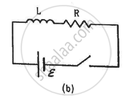
The switches in figure (a) and (b) are closed at t = 0 and reopened after a long time at t = t0.
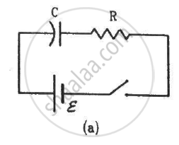
(a) The charge on C just after t = 0 is εC.
(b) The charge on C long after t = 0 is εC.
(c) The current in L just before t = t0 is ε/R.
(d) The current in L long after t = t0 is ε/R.
Calculate the dimensions of (a) \[\int \overrightarrow{E} . d \overrightarrow{l,}\] (b) vBl and (c) \[\frac{d \Phi_B}{dt}.\] The symbols have their usual meaning.
Figure shows a wire sliding on two parallel, conducting rails placed at a separation l. A magnetic field B exists in a direction perpendicular to the plane of the rails. What force is necessary to keep the wire moving at a constant velocity v?
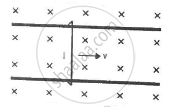
Figure shows a long U-shaped wire of width l placed in a perpendicular magnetic field B. A wire of length l is slid on the U-shaped wire with a constant velocity v towards right. The resistance of all the wires is r per unit length. At t = 0, the sliding wire is close to the left edge of the U-shaped wire. (a) Calculate the force needed to keep the sliding wire moving with a constant velocity v. (b) If the force needed just after t = 0 is F0, find the time at which the force needed will be F0/2.0
The following diagram shows a fixed coil of several turns connected to a center zero galvanometer G and a magnet NS which can move in the direction shown in the diagram.
- Describe the observation in the galvanometer if
- The magnet is moved rapidly,
- The magnet is kept still after it has moved into the coil
- The magnet is then rapidly pulled out the coil.
- How would the observation in (i) of part (a) change if a more powerful magnet is used?
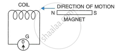
Fig. shows a simple form of an A.C. generator.

(a) Name the parts labeled A and B.
(b) What would be the effect of doubling the number of turns on the coil if the speed of rotation remains unchanged?
(c) Which of the output terminals is positive if the coil is rotating in the
direction shown in the diagram (anticlockwise)?
( d ) What is the position of the rotating coil when p.d. across its ends is zero? Explain why p.d. is zero when the coil is at this position .
(e) Sketch a graph showing how the p.d. across the ends of the rotating coil varies with time for an A.C. dynamo.
( f) On th e same sheet of paper and vertically below the first graph using the same time scale, sketch graphs to show the effect of
(i) Doubling the speed of rotation and at the same time keeping
the field and the number of turns constant,
(ii ) Doubling the number of turns on the coil and at the same time
doubling the speed of rotation of the coil, keeping th e speed
constant.
Fill in the blanks by writing (i) Only soft iron, (ii) Only steel, (iii) Both soft-iron and steel for the material of core and/or magnet.
A. C. generator______.
State the condition at which we say the two coils kept close to each other are perfectly coupled with each other.
Using Ampere's law, obtain an expression for the magnetic induction near a current-carrying straight infinitely long wire.
Observe the given figure of Fleming’s Right Hand Rule and write the labels of A and B correctly.
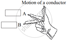
Write the two names in the following diagram.
Right hand thumb rule.
A square coil of side 30 cm with 500 turns is kept in a uniform magnetic field of 0.4 T. The plane of the coil is inclined at an angle of 30° to the field. Calculate the magnetic flux through the coil.
The magnetic flux passing through a coil perpendicular to its plane is a function of time and is given by OB = (2t3 + 4t2 + 8t + 8) Wb. If the resistance of the coil is 5 Ω, determine the induced current through the coil at a time t = 3 second.
An induced current of 2.5 mA flows through a single conductor of resistance 100 Ω. Find out the rate at which the magnetic flux is cut by the conductor.
A 50 cm long solenoid has 400 turns per cm. The diameter of the solenoid is 0.04 m. Find the magnetic flux linked with each turn when it carries a current of 1 A.
An alternating emf of 0.2 V is applied across an L-C-R series circuit having R = 4Q, C = 80µF, and L = 200 mH. At resonance the voltage drop across the inductor is
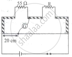
Shown in the figure below is a metre bridge set up with null deflection in the galvanometer. The value of the unknown resistance R is ______
The condition for the praenomen of electromagnetic induction is that there must be a relative motion between ____________.
Name some equipment that uses electromagnetism for functioning.
A 0.4 m wire, stretched horizontally, carries an electric current of 15 A, in a magnetic field whose magnetic field intensity is 0.1 N/Am. What is the magnitude of the wire?
A conductor of length 50 cm carrying a current of 5 A is placed perpendicular to a magnetic field of induction 2×10 -3T. Find the force on the conductor.
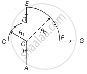
In the current carrying conductor (AOCDEFG) as shown, the magnetic induction at point O is ______.
(R1 and R2 are radii of CD and EF respectively. l = current in the loop, μ0 = permeability of free space)