Advertisements
Online Mock Tests
Chapters
1: Force
2: Work, Energy and Power
▶ 3: Machines
LIGHT
4: Refraction of Light at Plane Surfaces
5: Refraction through a Lens
6: Spectrum
SOUND
7: Sound
ELECTRICITY AND MAGNETISM
8: Current Electricity
9: Household Circuits
10: Electro-Magnetism
HEAT
11: Calorimetry
MODERN PHYSICS
12: Radioactivity
![Selina solutions for Physics [English] Class 10 ICSE chapter 3 - Machines - Shaalaa.com](/images/physics-english-class-10-icse_6:4c973dd038c545c9a2b6db170ad2f542.jpg "Selina solutions for Physics [English] Class 10 ICSE chapter 3 - Machines")
Advertisements
Solutions for Chapter 3: Machines
Below listed, you can find solutions for Chapter 3 of CISCE Selina for Physics [English] Class 10 ICSE.
Selina solutions for Physics [English] Class 10 ICSE 3 Machines EXERCISE - 3 (A) [Pages 57 - 60]
What do you understand by a simple machine?
State the principle of an ideal machine.
State four ways in which machines are useful to us.
Name a machine for each of the following uses:
- to multiply the force,
- to change the point of application of force,
- to change the direction of force,
- to obtain the gain in speed.
What is the purpose of a jack in lifting a car by it?
What do you understand by an ideal machine?
How does ideal machine differ from a practical machine ?
Explain the term mechanical advantage.
State the unit of mechanical advantage.
Define the term velocity ratio.
State the unit of velocity ratio.
How is mechanical advantage related to the velocity ratio for an ideal machine?
How is mechanical advantage related to velocity ratio for a practical machine?
Define the term efficiency of a machine.
Give two reasons for a machine not to be 100% efficient?
When does a machine act as (a) a force multiplier, (b) a speed multiplier? Can a machine act as a force multiplier and a speed multiplier simultaneously?
A machine works as a
- force multiplier,
- speed multiplier.
In each case, state whether the velocity ratio is more than or less than 1.
- State the relationship between mechanical advantage, velocity ratio and efficiency.
- Name the term that will not change for a machine of a given design.
Derive a relationship between mechanical advantage, velocity ratio and efficiency of a machine.
How is the mechanical advantage related with the velocity ratio for an actual machine? State whether the efficiency of such a machine is equal to 1, less than 1 or more than 1.
State one reason why is mechanical advantage less than the velocity ratio for an actual machine.
What is a lever?
State the principle of a lever?
Write down a relation expressing the mechanical advantage of a lever.
Name the three classes of levers and state how are they distinguished. Give two examples of each class.
Give one example of a class I lever where the mechanical advantage is more than 1.
Give one example of a class I lever where mechanical advantage is less than 1.
What is the use of the lever if its mechanical advantage is
- more than 1,
- equal to 1, and
- less than 1?
Both a pair of scissors and a pair of pliers belong to the same class of levers. Name the class of lever. Which one has the mechanical advantage less than 1?
Explain why scissors for cutting cloth may have blades longer than the handles, but shears for cutting metals have short blades and long handles.
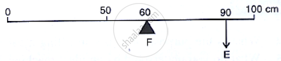
Shows a uniform metre scale of weight W supported on a fulcrum at the 60 cm mark by applying the effort E at the 90 cm mark.
- State with reason whether the weight W of the scale is greater than, less than or equal to the effort E.
- Find the mechanical advantage in an ideal case.
Which type of lever has a mechanical advantage always more than one? Give one example. What change can be made in this lever to increase its mechanical advantage?
Draw a diagram of a lever which is always used as a force multiplier. How is the effort arm related to the load arm in such a lever?
Explain why the mechanical advantage of a class II of lever is always more than 1.
Draw a labelled diagram of a class II lever. Give one example of such a lever.
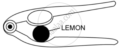
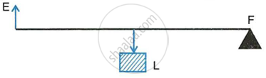
Shows a lemon crusher.
- In the diagram, mark the position of the fulcrum F and the line of action of load L and effort E.
- Name the class of lever
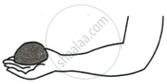
The diagram below shows a rod lifting a stone.
- Mark position of fulcrum F and draw arrows to show the directions of load L and effort E.
- What class of lever is the rod?
- Give one more example of the same class of lever stated in part (b).

State the kind of lever which always has mechanical advantage less than 1. Draw a labelled diagram of such a lever.
Explain why the mechanical advantage of the class III type of lever is always less than 1.
Class III levers have mechanical advantage less than one. Why are they then used?
Draw a labelled sketch of a class III lever. Give one example of this kind of lever.
State the class of levers and the relative positions of load (L) effort (E) and fulcrum (F) in a bottle opener?
State the class of levers and the relative positions of load (L), effort (E) and fulcrum (F) in sugar tongs.
Draw diagrams to illustrate the position of fulcrum load and effort, in the following:
A seesaw
Draw a diagram to illustrate the position of fulcrum load and effort, in the following:
A common balance
Draw a diagram to illustrate the position of fulcrum load and effort, in the following:
A nut cracker
Draw a diagram to illustrate the position of fulcrum load and effort, in the following:
Forceps
Classify the following into levers:
A door
Class I
Class II
Class III
Classify the following into levers:
A catapult
Class I
Class II
Class III
Classify the following into levers:
Claw hammer
Class I
Class II
Class III
Classify the following into levers:
Wheel barrow
Class I
Class II
Class III
Classify the following into levers:
A fishing rod
Class I
Class II
Class III
Classify the following into levers:
Sugar tongs
Class I
Class II
Class III
What type of lever is formed by the human body while raising a load on the palm?
What type of lever is formed by the human body while raising the weight of body on toes?
Indicate the positions of load L, effort E and fulcrum F in the forearm shown alongside in following figure. Name the class of lever.
Give an example of each class of lever in a human body.
Complete the following sentences:
Mechanical advantage = ______ × velocity ratio.
In class II lever, effort arm is ______ than the load arm.
A pair of scissors is a _____ multiplier.
MULTIPLE CHOICE TYPE
Mechanical advantage (M.A.), load (L) and effort (E) are related as ______.
M.A. = L × E
M.A. × E = L
E = M.A. × L
None of these
The correct relationship between the mechanical advantage (M.A.), the velocity ratio (V.R.) and the efficiency (n) is ______.
M.A. = η × V.R.
V.R. = η × M.A.
η = M.A. × V.R.
None of these
State the incorrect statement:
A machine always has efficiency less than 100%.
The mechanical advantage of a machine can be less than 1.
A machine can be used as speed multiplier.
A machine can have the mechanical advantage greater than the velocity ratio.
The lever for which the mechanical advantage is less than 1 has :
Fulcrum at mid-point between load and effort.
Load between effort and fulcrum.
Effort between fulcrum and load.
Load and effort acting at the same point.
Class II levers are designed to have ______.
M.A. = V.R.
M.A. > V.R.
M.A. > 1
M.A. < 1
NlJMERICALS
A crowbar of length 120 cm has its fulcrum situated at a distance of 20 cm from the load. Calculate the mechanical advantage of the crowbar.
A pair of scissors has its blades 15 cm long, while its handles are 7.5 cm long. What is its mechanical advantage?
A force of 5 kgf is required to cut a metal sheet. A pair of shears used for cutting the metal sheet has its blades 5 cm long, while its handles is 10 cm long. What effort is needed to cut the sheet?
The figure below shows a lever in use:
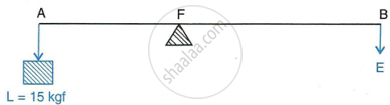
- To which class of lever does it belong?
- If AB = 1 m, AF = 0.4 m, find its mechanical advantage.
- Calculate the value of E.
A man uses a crowbar of length 1.5 m to raise a load of 75 kgf by putting a sharp edge below the bar at a distance 1 m from his hand.
- Draw a diagram of the arrangement showing the fulcrum (F), load (L) and effort (E) with their directions.
- State the kind of lever.
- Calculate:
- load arm,
- effort arm,
- mechanical advantage and
- the effort needed.
A pair of scissors is used to cut a piece of a cloth by keeping it at a distance 8.0 cm from its rivet and applying an effort of 10 kgf by fingers at a distance 2.0 cm from the rivet.
- Find:
- the mechanical advantage of scissors and
- the load offered by the cloth.
- How does the pair of scissors act: as a force multiplier or as speed multiplier?
A 4 m long rod of negligible weight is to be balanced about a point 125 cm from one end and a load of 18 kgf is suspended at a point 60 cm from the support on the shorter arm.
- If a weight W is placed at a distance of 250 cm from the support on the longer arm to balance the rod, find W.
- If a weight 5 kgf is kept to balance the rod, find its position.
- To which class of lever does it belong?
A lever of length 9 cm has its load arm 5 cm long and the effort arm is 9 cm long.
- To which class does it belong?
- Draw a diagram of the lever showing the position of fulcrum F and directions of both the load L and effort E.
- What is the mechanical advantage and velocity ratio if the efficiency is 100%?
- What will be the mechanical advantage and velocity ratio if the efficiency becomes 50%?
The diagram below shows a lever in use:
- To which class of levers does it belong?
- Without changing the dimensions of the lever, if the load is shifted towards the fulcrum what happens to the mechanical advantage of the lever?
Figure below shows a wheel barrow of mass 15 kgf carrying a load of 30 kgf with its centre of gravity at A. The points B and C are the centre of wheel and tip of the handle such that the horizontal distance AB = 20 cm and AC = 40 cm.
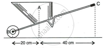
Find:
- the load arm,
- the effort arm,
- the mechanical advantage and
- the minimum effort required to keep the leg just off the ground.
The figure below shows the use of a lever.

- State the principle of moments as applied to the above lever.
- To which class of lever does it belong ? Give an example of this class of lever.
- If FA = 10 cm, AB = 490 cm calculate:
- the mechanical advantage and
- the minimum effort required to lift the load (= 50 N).
A fire tongs has arms 20 cm long. It is used to lift a coal of weight 1.5 kgf by applying an effort at a distance 15 cm from the fulcrum. Find:
- the mechanical advantage of fire tongs and
- the effort needed.
Selina solutions for Physics [English] Class 10 ICSE 3 Machines EXERCISE - 3 (B) [Pages 66 - 69]
What is a fixed pulley?
State one use of a fixed pulley.
What is the ideal mechanical advantage of a single fixed pulley? Can it be used as a force multiplier?
Name the pulley which has no gain in mechanical advantage. Explain, why is such a pulley then used?
What is the velocity ratio of a single fixed pulley?
In a single fixed pulley, if the effort moves by a distance x downwards, by what height is the load raised upwards?
What is a single movable pulley?
What is the mechanical advantage of a single movable pulley in the ideal case?
Name the type of single pulley that has an ideal mechanical advantage equal to 2. Draw a labelled diagram of the pulley mentioned by you.
Give two reasons why the efficiency of a single movable pulley system is not 100%.
In which direction does the force need to applied, when a single pulley is used with a mechanical advantage greater than one? How can you change the direction of force applied without altering its mechanical advantage? Draw a labelled diagram of the system.
What is the velocity ratio of a single movable pulley? How does the friction in the pulley bearing affect it?
In a single movable pulley, if the effort moves by a distance x upwards, by what height is the load raised?
Draw a labelled diagram of an arrangement of two pulleys, one fixed and other movable. In the diagram, mark the directions of all forces acting on it. What is the ideal mechanical advantage of the system? How can it be achieved?
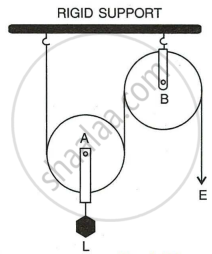
The diagram below shows a pulley arrangement.
- Name the pulleys A and B.
- In the diagram, mark the direction of tension on each strand of string.
- What is the purpose of the pulley B?
- If the tension is T, deduce the relation between
- T and E, and
- E and L.
- What is the velocity ratio of the arrangement?
- Assuming that the efficiency of the system is 100%, what is the mechanical advantage?
Differentiate between a single fixed pulley and a single movable pulley.
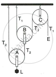
The diagram below shows an arrangement of three pulleys A, B, and C. The load is marked as L and the effort as E.
- Name the Pulleys A, B, and C.
- Mark in the diagram the directions of load (L), effort (E) and tension T1 and T2 in the two strings.
- How are the magnitudes of L and E related to the tension T1?
- Calculate the mechanical advantage and velocity ratio of the arrangement.
- What assumptions have you made in parts (c) and (d)?
Draw a diagram of a combination of three movable pulleys and one fixed pulley to lift up a load. In the diagram, show the directions of load, effort and tension in each strand. Find:
- mechanical advantage,
- Velocity ratio and
- efficiency of the combination in ideal situation.
Draw a diagram of a block and tackle system of pulleys having a velocity ratio of 5. In your diagram indicate clearly the points of application and the directions of the load L and effort E. Also mark the tension T in each strand.
Give a reason for the following:
In a single fixed pulley, the velocity ratio is always more than the mechanical advantage.
Give reason for the following:
The efficiency of a movable pulley is always less than 100%.
Give reason for the following:
In case of a block and tackle system, the mechanical advantage increases with the increase in the number of pulleys.
Give reason for the following:
The lower block of a block and tackle pulley system must be of negligible weight
Name a machine which is used to multiply force.
Name a machine which is used to multiply speed.
Name a machine which is used to change the direction for force applied.
State whether the following statements are true or false.
The velocity ratio of a single fixed pulley is always more than 1.
True
False
The velocity ratio of a single movable pulley is always 2.
True
False
The velocity ratio of a combination of n movable pulleys with a fixed pulley is always 2n.
True
False
The velocity ratio of a block and tackle system is always equal to the number of strands of the tackle supporting the load.
True
False
MULTIPLE CHOICE TYPE
A single fixed pulley is used because it ______.
Has a mechanical advantage greater than 1
Has a velocity ratio less than 1
Gives 100% efficiency
Helps to apply the effort in a convenient direction.
The mechanical advantage of an ideal single movable pulley is ______.
1
2
less than 2
less than 1
A movable pulley is used as ______.
a force multiplier
a speed multiplier
a device to change the direction of effort
an energy multiplier
NUMERICALS
A Woman draws water from a well using a fixed pulley. The mass of bucket and water together is 6 kg. The force applied by the woman is 70 N. Calculate the mechanical advantage. (Take g = 10 m s-2)
A fixed pulley is driven by a 100 kg mass falling at a rate of 8.0 m in 4.0s. It lifts a load of 75.0 kgf. Calculate the power input to the pulley taking the force of gravity on 1 kg as 10 N.
A fixed pulley is driven by a 100 kg mass falling at a rate of 8.0 m in 4.0 s. It lifts a load of 75.0 kgf. Calculate the efficiency of the pulley.
A fixed pulley is driven by a 100 kg mass falling at a rate of 8.0 m in 4.0 s. It lifts a load of 75.0 kgf. Calculate : the height to which the load is raised in 4.0 s.
A single fixed pulley and a movable pulley both are separately used to lift a load of 50 kgf to the same height. Compare the efforts applied in an ideal situation.
In a block and tackle system consisting of 3 pulleys, a load of 75 kgf is raised with an effort of 25 kgf. Find:
- the mechanical advantage,
- velocity ratio and
- efficiency.
A block and tackle system has 5 pulleys. If an effort 0f 1000 N is needed in the downward direction to raise a load of 4500 N, calculate:
- the mechanical advantage
- the velocity ratio, and
- the efficiency of the system.
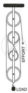
In following figure, draw a tackle to lift the load by applying the force in the downward direction.
- Mark in the diagram the direction of load L and effort E.
- If the load is raised by 1 m, through what distance will the effort move?
- State how many strands of tackle are supporting the load?
- What is the mechanical advantage of the system?
A pulley system has a velocity ratio 3. Draw a diagram showing the point of application and direction of load (L), effort (E) and tension (T). It lifts a load of 150 N by an effort of 60 N. Calculate its mechanical advantage. Is the pulley system ideal? Give reason.
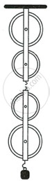
In following figure, shows a system of four pulleys, The upper two pulleys are fixed and the lower two are movable.
- Draw a string around the pulleys. Also show the place and direction in which the effort if applied.
- What is the velocity ratio of the system?
- How are load and effort of the pulley system related?
- What assumption do you make in arriving at your answer in part (c)?
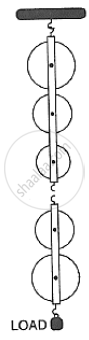
In following figure, shows a block and tackle system of pulleys used to lift a load.
- How many strands of tackle are supporting the load?
- Draw arrows to represent tension T in each strand.
- What is the mechanical advantage of the system?
- When load is pulled up by a distance 1 m, how far does the effort end move?
- How much effort is needed to lift a load of 100 N?
- What will be it's V.R. if the weight of the movable block is doubled?
A block and tackle system has the velocity ratio 3. Draw a labelled diagram of the system indicating the points of application and the directions of load L and effort E. A man can exert a pull of 200 kgf. What is the maximum load he can raise with this pulley system is its efficiency is 60%?
A block and tackle system has the velocity ratio 3. Draw a labelled diagram of the system indicating the points of application and the directions of load L and effort E. A man can exert a pull of 200 kgf. If the effort end moves a distance 60 cm, what distance does the load move?
You are given four pulleys and three strings. Draw a neat and labelled diagram to use them so as to obtain a maximum mechanical advantage equal to 8. In you diagram make the directions of load, effort and tension in each strand. What assumptions have you made to obtain the required mechanical advantage?
Solutions for 3: Machines
Selina solutions for Physics [English] Class 10 ICSE chapter 3 - Machines
Shaalaa.com has the CISCE Mathematics Physics [English] Class 10 ICSE CISCE solutions in a manner that help students grasp basic concepts better and faster. The detailed, step-by-step solutions will help you understand the concepts better and clarify any confusion. Selina solutions for Mathematics Physics [English] Class 10 ICSE CISCE 3 (Machines) include all questions with answers and detailed explanations. This will clear students' doubts about questions and improve their application skills while preparing for board exams.
Further, we at Shaalaa.com provide such solutions so students can prepare for written exams. Selina textbook solutions can be a core help for self-study and provide excellent self-help guidance for students.
Concepts covered in Physics [English] Class 10 ICSE chapter 3 Machines are Machines, Simple Machines, Machines (Numerical), A Lever, A Pulley, Principle of Machine, Relationship between efficiency (ղ), mechanical advantage (M.A.) and velocity ratio (VR), Types of Levers, Single Fixed Pulley, Technical Terms Related to a Machine, Single Movable Pulley, Combination of Pulleys, Examples of Each Class of Levers as Found in the Human Body, Machines, Simple Machines, Machines (Numerical), A Lever, A Pulley, Principle of Machine, Relationship between efficiency (ղ), mechanical advantage (M.A.) and velocity ratio (VR), Types of Levers, Single Fixed Pulley, Technical Terms Related to a Machine, Single Movable Pulley, Combination of Pulleys, Examples of Each Class of Levers as Found in the Human Body.
Using Selina Physics [English] Class 10 ICSE solutions Machines exercise by students is an easy way to prepare for the exams, as they involve solutions arranged chapter-wise and also page-wise. The questions involved in Selina Solutions are essential questions that can be asked in the final exam. Maximum CISCE Physics [English] Class 10 ICSE students prefer Selina Textbook Solutions to score more in exams.
Get the free view of Chapter 3, Machines Physics [English] Class 10 ICSE additional questions for Mathematics Physics [English] Class 10 ICSE CISCE, and you can use Shaalaa.com to keep it handy for your exam preparation.
