Topics
Electronic Components/ Study of Components and Circuits
- Introduction to Electronic Components
- Classification Of Components
- Resistors
- Types of Resistors
- Capacitors
- Types of Capacitors
- Inductors
- Basics of Transformers
- Basics of Semiconductor Devices
- PN Junction Diode
- Half Wave Rectifier
- Types of diodes
- Transistors
- Transistor Amplifier
- Basic of Transistor as a Switch
- Switch Mode power Supply (SMPS)
- Classification of IC’S
Logic Gates and Sequential Circuit
- Introduction of Logic gates and sequential circuits
- Basics of Logic Gates
- Types of gates
- Odd/Even Parity
- DE-MORGAN'S Theorem
- NAND Gate is an Universal Building Block
- HALF ADDER AND FULL ADDER
- Multiplexers
- Demultiplexer
- Encoder
- Decoder
- FLIP-FLOPS
- Counters
- Shift Registers
Functional Hardware of Pc
Peripheral Devices
- Introduction
- Characteristics of IC’s
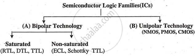
Classification of IC’S
These digital IC' s can be classified according to the semiconductor device, which is basically used as a basic block in the manufacturing process of microprocessors and other IC' s. These IC' s are classified into two groups.
Characteristics Of IC's
The performance · arid the quality of an integrated chip or IC · depend on their characteristics:
- Propagation Delay (Speed): The execution time of a microprocessor instruction is determined by propagation delay, defined as the “the time required to change the output from one logic state to other logic state after input is applied”. For example, TTL logic family has a 10 ns propagation delay.
- Power Dissipation: Power dissipation, related to propagation delay, is the “power (in mW) a gate in an IC dissipates.” Low power dissipation is desirable to reduce heat, cooling needs, and costs, requiring minimal voltage and current. Manufacturers specify power dissipation in mW.
- Figure Of Merit: The figure of merit, indicating overall performance, “is the product of propagation delay and power dissipation.” Increasing resistance reduces power dissipation but increases delay, and vice versa. It's measured in "pJ".
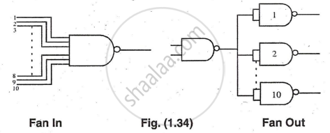
- Fan In - Fan Out: The capacity of a gate to drive loads is expressed as fan-out, defined as the maximum number of gates (loads) from the same family that can be driven reliably. Fan-in is the number of inputs to a gate. Fan-out is also called the loading factor.
CMOS & TTL Family
|
CMOS Family |
TTL Family |
|
It is an unipolar family |
It is a bi-polar family |
|
Propagation delay: About 10 ns |
Propagation delay: 15 ns to 300 ns |
|
Power dissipation: 10 mW |
Power dissipation: 1 µW |
|
Numbering system is 74CXX. |
Numbering system is 74CXX. |
|
Figure of Merit is 0.002 |
Figure of Merit is 100 |
|
Supply Voltage 3V to 18V |
Supply Voltage is 4.75V to 5.25V |
|
Fan-in Fan-out is >50 |
Fan-in Fan-out is 10. |
