Topics
Electronic Components/ Study of Components and Circuits
- Introduction to Electronic Components
- Classification Of Components
- Resistors
- Types of Resistors
- Capacitors
- Types of Capacitors
- Inductors
- Basics of Transformers
- Basics of Semiconductor Devices
- PN Junction Diode
- Half Wave Rectifier
- Types of diodes
- Transistors
- Transistor Amplifier
- Basic of Transistor as a Switch
- Switch Mode power Supply (SMPS)
- Classification of IC’S
Logic Gates and Sequential Circuit
- Introduction of Logic gates and sequential circuits
- Basics of Logic Gates
- Types of gates
- Odd/Even Parity
- DE-MORGAN'S Theorem
- NAND Gate is an Universal Building Block
- HALF ADDER AND FULL ADDER
- Multiplexers
- Demultiplexer
- Encoder
- Decoder
- FLIP-FLOPS
- Counters
- Shift Registers
Functional Hardware of Pc
Peripheral Devices
- Introduction
- Half Adder
- Full Adder
- Binary Adder
- Ex-OR Inverter
- Adder / Subtractor
HALF ADDER AND FULL ADDER
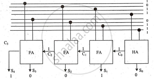
In computer circuits, the arithmetic section includes adders, subtractors, multipliers, and integrators. A four-bit addition uses one half adder for the LSB and three full adders for the remaining bits.
Where 1 binary digit = 1 bit, 4 bits = 1 Nibble and 1 byte = 8 Bits
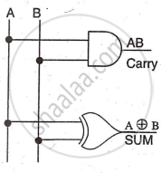
Half Adder
It can add two bits, suitable only for LSB column addition. The circuit design is based on the two-bit addition truth table, focusing on carry and sum outputs.
Boolean Equation: i) CARRY= `A•B` ii) SUM = `A⊕B`
Circuit Diagram:
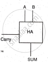
Symbol:
Full Adder & Binary Adder
In higher columns, a carry from the previous column may occur, requiring three-bit addition, which a full adder can perform. The full adder circuit, designed using a truth table, uses three AND gates for the carry output and a three-input XOR gate for the sum output.
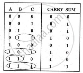
Truth Table:
Circuit Diagram:
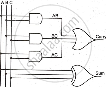
Boolean Equation: i) CARRY = AB+ BC+ AC (Refer dotted circles in truth table)
ii) SUM = `A⊕B⊕C`
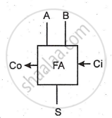
Symbol of Full Adder:
Binary Adder (Block Diagram):
Ex-OR Inverter
An Ex- OR gate acts as an inverter when one input is high, and the other is variable. If A = 0, Y = 1; if A = 1, Y = 0. Four Ex-OR gates can find the one's complement of input ABCD with a common high input.
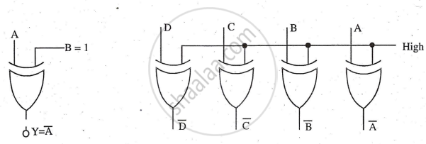
Note that when the common signal is low to this circuit then the EX-OR circuit output does not change, it is ABCD only. The common line can be used as control so that when the line is low it sends ABCD and when it is high it sends
