Topics
Electronic Components/ Study of Components and Circuits
- Introduction to Electronic Components
- Classification Of Components
- Resistors
- Types of Resistors
- Capacitors
- Types of Capacitors
- Inductors
- Basics of Transformers
- Basics of Semiconductor Devices
- PN Junction Diode
- Half Wave Rectifier
- Types of diodes
- Transistors
- Transistor Amplifier
- Basic of Transistor as a Switch
- Switch Mode power Supply (SMPS)
- Classification of IC’S
Logic Gates and Sequential Circuit
- Introduction of Logic gates and sequential circuits
- Basics of Logic Gates
- Types of gates
- Odd/Even Parity
- DE-MORGAN'S Theorem
- NAND Gate is an Universal Building Block
- HALF ADDER AND FULL ADDER
- Multiplexers
- Demultiplexer
- Encoder
- Decoder
- FLIP-FLOPS
- Counters
- Shift Registers
Functional Hardware of Pc
Peripheral Devices
- Introduction to encoder
- BCD encoder
Encoder & Decoder
Encoder
A digital circuit like a calculator converts decimal inputs (0-9) to binary using an encoder for processing. After operations like addition with a binary adder, the binary output is converted back to decimal and displayed, typically with a 7-segment display. Computers use similar encoders to convert input data to ASCII or BCD.
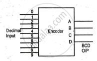
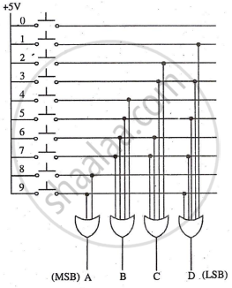
BCD Encoder
An encoder is a combinational circuit that converts standard input into coded signals. A BCD encoder converts decimal numbers (0-9) into BCD code using ten switches. For example, pressing '0' outputs ABCD = 0000, and pressing '3' outputs ABCD = 0011.
Circuit Diagram:
Truth Table:
|
Decimal input |
BCD output |
|
0 |
0000 |
|
1 |
0001 |
|
2 |
0010 |
|
3 |
0011 |
|
4 |
0100 |
|
5 |
0101 |
|
6 |
0110 |
|
7 |
0111 |
|
8 |
1000 |
|
9 |
1001 |
Decoder
A decoder is a combinational logic circuit that converts an encoded signal back to its original form. For example, a BCD decoder converts BCD code into a decimal number. It performs the reverse function of an encoder, accepting coded inputs and generating the desired standard output. 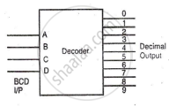
BCD to Decimal Decoder
The select lines of a demultiplexer can serve as BCD inputs (DCBA), with ten outputs (Y0 to Y9). This setup is called a 1-of-10 decoder, as only one output is high at a time. For active-low output, replace AND gates with NAND gates.
Circuit Diagram:
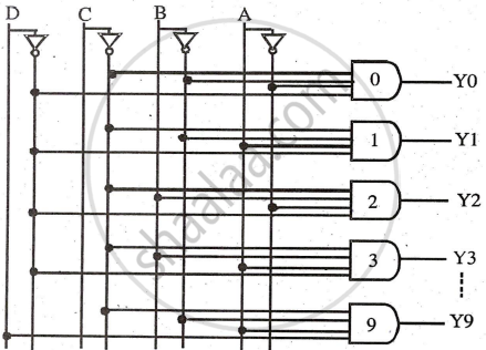
Working: When BCD input is DCBA = 0000, the first AND gate is enabled, making Y0 = 1. For DCBA = 0001, the second AND gate is enabled, making Y1 = 1. Each BCD input produces one high output. For DCBA = 1001 (9), Y9 will be high.
