Topics
Electronic Components/ Study of Components and Circuits
- Introduction to Electronic Components
- Classification Of Components
- Resistors
- Types of Resistors
- Capacitors
- Types of Capacitors
- Inductors
- Basics of Transformers
- Basics of Semiconductor Devices
- PN Junction Diode
- Half Wave Rectifier
- Types of diodes
- Transistors
- Transistor Amplifier
- Basic of Transistor as a Switch
- Switch Mode power Supply (SMPS)
- Classification of IC’S
Logic Gates and Sequential Circuit
- Introduction of Logic gates and sequential circuits
- Basics of Logic Gates
- Types of gates
- Odd/Even Parity
- DE-MORGAN'S Theorem
- NAND Gate is an Universal Building Block
- HALF ADDER AND FULL ADDER
- Multiplexers
- Demultiplexer
- Encoder
- Decoder
- FLIP-FLOPS
- Counters
- Shift Registers
Functional Hardware of Pc
Peripheral Devices
- Combinational Circuits
- Introduction to multiplexer
- 4:1 Multiplexer
Notes
Multiplexer
A multiplexer, or data selector, is a combinational circuit that connects multiple inputs to a single output line, simplifying and economizing the system. It uses 'n' input data lines, 'm' control/selector lines, and one output line.
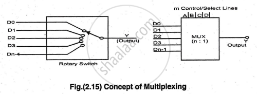
For selecting one of the 'n' inputs to the output of MUX, it requires minimum 'm' lines and 'm' can be calculated by using an equation.
2m = n ....... (formula)
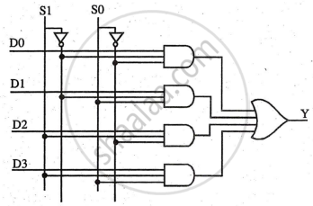
4:1 Multiplexer & Working
As stated earlier, it has 4 input lines (D0, D1, D2, D3) two control lines (S1 S0) (called select lines) and one output denoted by 'Y'.
Circuit Diagram
Truth Table
|
A |
B |
Y |
|
0 |
0 |
D0 |
|
0 |
1 |
D1 |
|
1 |
0 |
D2 |
|
1 |
1 |
D3 |
Working:
- Control word 00 (S1=0, S0=0): Enables first AND gate, Y = D0.
- Control word 01 (S1=0, S0=1): Enables second AND gate, Y = D1.
- Control word 10 (S1=1, S0=0): Enables third AND gate, Y = D2.
- Control word 11 (S1=1, S0=1): Enables fourth AND gate, Y = D3.
Only one AND gate is enabled at a time, connecting one data line to the output.
Demultiplexers
A demultiplexer takes one input and distributes it to several outputs, with the control word determining the connected output. It can also function as a decoder, such as a binary to decimal decoder.
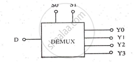
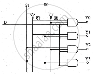
1:4 Demultiplexer & Working
1: 4 DEMUX has 1 input (D), which can be connected to four outputs (Y0, Y1, Y2, Y3) but one at a time. The output is selected by a control word or code present on the select lines as explained earlier since n = 4 and 2m = 4, the number of select lines must be two S0 and S1.
Circuit Diagram:
Truth Table
|
A |
B |
D |
|
0 |
0 |
Y0 |
|
0 |
1 |
Y1 |
|
1 |
0 |
Y2 |
|
1 |
1 |
Y3 |
