Topics
Electronic Components/ Study of Components and Circuits
- Introduction to Electronic Components
- Classification Of Components
- Resistors
- Types of Resistors
- Capacitors
- Types of Capacitors
- Inductors
- Basics of Transformers
- Basics of Semiconductor Devices
- PN Junction Diode
- Half Wave Rectifier
- Types of diodes
- Transistors
- Transistor Amplifier
- Basic of Transistor as a Switch
- Switch Mode power Supply (SMPS)
- Classification of IC’S
Logic Gates and Sequential Circuit
- Introduction of Logic gates and sequential circuits
- Basics of Logic Gates
- Types of gates
- Odd/Even Parity
- DE-MORGAN'S Theorem
- NAND Gate is an Universal Building Block
- HALF ADDER AND FULL ADDER
- Multiplexers
- Demultiplexer
- Encoder
- Decoder
- FLIP-FLOPS
- Counters
- Shift Registers
Functional Hardware of Pc
Peripheral Devices
- Introduction to Counters
- 4-Bit Binary Counter (MOD-16)
- Decade Counter (MOD - 10)
Counters
An electronic digital counter is a flip-flop circuit that counts the number of applied clock pulses, producing binary output in sequence. The total number of states, denoted by 'M', specifies the modulus of the counter. The required number of flip-flops is calculated by the formula:
M = 2n
where n= number of flip-flops.
4-Bit Binary Counter (MOD-16)
Flip-flops are crucial for counters, which count input pulses. A counter circuit uses four cascaded JK flip-flops (A, B, C, D) in toggle mode (J = K = high) with a square wave clock input.
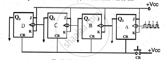
Working
Assume the outputs are initially cleared to 0000 using the 'CR' switch.
- At the first clock pulse, flip-flop A's output goes high (Q0 = 1). Flip-flops B, C, and D remain unchanged, resulting in a counter output of 0001.
- At the second clock pulse, flip-flop A's output goes low (Q0 = 0), causing flip-flop B to go high (Q1 = 1). Flip-flops C and D remain unchanged, resulting in a counter output of 0010.
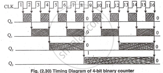
Each flip-flop changes state at the negative edge of its clock pulse. The counter increments up to 1111 and then resets to 0000 at the 17th pulse.
Truth Table:
|
Pulse |
Q3 |
Q2 |
Q1 |
Q0 |
|
1 |
0 |
0 |
0 |
0 |
|
2 |
0 |
0 |
1 |
1 |
|
6 |
0 |
1 |
1 |
0 |
|
7 |
0 |
1 |
1 |
1 |
|
8 |
1 |
0 |
0 |
0 |
|
9 |
1 |
0 |
0 |
1 |
|
10 |
1 |
0 |
1 |
0 |
|
11 |
1 |
0 |
1 |
1 |
|
12 |
1 |
1 |
0 |
0 |
|
13 |
1 |
1 |
0 |
1 |
|
14 |
1 |
1 |
1 |
0 |
|
15 |
1 |
1 |
1 |
1 |
|
16 |
0 |
0 |
0 |
0 (Reset) |
|
17 |
0 |
0 |
0 |
1(Recounting) |
This 4-bit binary counter is called a ripple and asynchronous counter, which means that all flip-flops do not trigger at the same time. Trigger flows through flip-flops ,like a ripple on water.
Decade Counter (MOD - 10)
The discussed binary counter is suitable for computers but inconvenient for decimal use, as it counts from 0 to 15. By adding feedback, it converts to a decade counter, counting from 0000 to 1001 and then resetting to 0000.
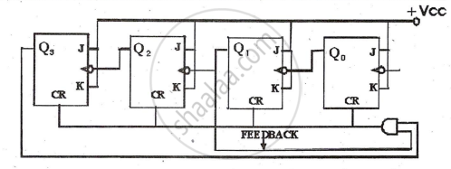
Working: The counter works in normal way as in 4-bit binary counter from pulse 1 to 9 between 0000 to 1001 and observe the timing diagram during these counts Q3 & Q1 never become 11 so that AND gate is disabled, it will not give CLR signal to the flip-flops. In other words for the count to 1001 the AND gate is disabled but at 10th pulse the output of the counter would be 1010 which will make AND gate enable and a high CLR pulse will reset the flip-flops to 0000.
Truth Table:
|
Pulse |
Q3 |
Q2 |
Q1 |
Q0 |
|
1 |
0 |
0 |
0 |
0 |
|
2 |
0 |
0 |
0 |
1 |
|
3 |
0 |
1 |
1 |
0 |
|
4 |
0 |
1 |
1 |
1 |
|
5 |
1 |
0 |
0 |
0 |
|
6 |
1 |
0 |
0 |
1 |
|
7 |
1 |
0 |
1 |
0 |
|
8 |
1 |
0 |
1 |
1 |
|
9 |
1 |
1 |
0 |
0 |
|
10 |
1 |
1 |
0 |
1 |
|
11 |
1 |
1 |
1 |
0 |
