Topics
Electronic Components/ Study of Components and Circuits
- Introduction to Electronic Components
- Classification Of Components
- Resistors
- Types of Resistors
- Capacitors
- Types of Capacitors
- Inductors
- Basics of Transformers
- Basics of Semiconductor Devices
- PN Junction Diode
- Half Wave Rectifier
- Types of diodes
- Transistors
- Transistor Amplifier
- Basic of Transistor as a Switch
- Switch Mode power Supply (SMPS)
- Classification of IC’S
Logic Gates and Sequential Circuit
- Introduction of Logic gates and sequential circuits
- Basics of Logic Gates
- Types of gates
- Odd/Even Parity
- DE-MORGAN'S Theorem
- NAND Gate is an Universal Building Block
- HALF ADDER AND FULL ADDER
- Multiplexers
- Demultiplexer
- Encoder
- Decoder
- FLIP-FLOPS
- Counters
- Shift Registers
Functional Hardware of Pc
Peripheral Devices
- Introduction
- Alpha and Beta of Transistor
- PNP Transistor
Transistors
A transistor, named from "transfer-of-resistor," controls current through bias. Bipolar transistors use both holes and electrons for current flow. There are two basic types of bipolar transistors (i) NPN transistor and (ii) PNP transistor.
Transistor consists of three semiconductor regions (either Silicon or Germanium) as follows ·
- Emitter- It is heavily doped and medium in size.
- Base - Lightly doped and thin in size.
- Collector - Medium doped and larger in size
Different ways of Biasing
Thus, transistor has two P-N junctions Emitter - Base (EB) and Base - Collector (BC). Hence there must be two batteries to apply bias across E-B junction and B-C junction. We can bias these two junctions in three different ways.
FF Bias: In (FF) method both junctions are forward biased so large current flows through transistor, transistor behaves as a low resistance, it does not give control action, and therefore this method is not useful. This, we get in saturation state
RR Bias: In (RR) method since both junctions are reverse biased, current through transistor is almost zero, transistor behaves as an insulator that is transistor is in 'cut off' which is also not useful state in amplifiers.
FR Bias: In the correct biasing method, the emitter-base junction is forward biased, and the base-collector junction is reverse biased, placing the transistor in the active region. A low voltage (VBE) biases the base-emitter, and a high voltage (VCE) biases the base-collector. Electrons flow from the emitter to the collector, with the emitter current (IE) nearly equal to the collector current (IC), following IE = IB + IC. Conventional current flows from collector to emitter.
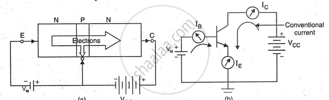
Alpha and Beta of Transistor
The relationship between emitter current (IE) and collector current (IC) is defined by alpha (α), while the relationship between base current (IB) and collector current is defined by beta (β). Beta (β) indicates that a small base current controls a large collector current.
Alpha= Collector Current/Emitter Current
Beta= Collector Current/Base Current
Transistor Amplifier
When it is used in amplifier it is operated in active region and avoids cut-off and saturation otherwise it produces distorted signal
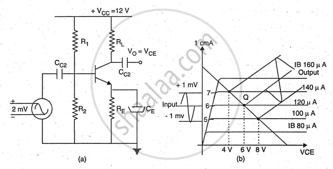
Refer to fig. (a), showing a single-stage amplifier with voltage divider bias using resistors R1 and R2. Coupling capacitors Cc1 and Cc2 couple the AC signal. RL is the collector load resistor. The input signal at the base is amplified at the collector, with the output taken w.r.t to ground. Fig shows input signal of ± 1m V is applied to a transistor amplifier and output is taken from collector to ground (V0 = VCE ). To understand how signal is amplified by transistor amplifier refer the graph shown by fig (b).
Voltage Gain = Change in output voltage/ Change in input voltage
Transistor as Switch
When used as a switch, a transistor operates in either cut-off or saturation, avoiding the active region. In digital circuits, like computer gates, it acts as an electronic switch, controlled by high or low input voltage at the base terminal.
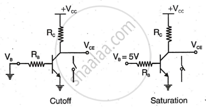
Case 1: When VB = 0, the base-emitter junction is reverse biased, putting the transistor in cut-off, equivalent to an open switch.
Case 2: When VB = +5V, the base-emitter junction is forward biased, putting the transistor in saturation, equivalent to a closed switch.
