Topics
Introduction to Microprocessors and Organization of 8085
Instruction Set and Programming of 8085
Introdcution to Inted X-86 Family
Introduction to Microcontroller
Networking Technology
- Introduction to Networking
- Types of Networks
- Multiplexing
- Study of Transmission media
- Coaxial cable (Cable Media)
- Twisted pair cable
- Fiber Optic Cable
- Unbounded (Wireless) Media
- Access Methods
- Network Topologies
- Ethernet (Network Architectures)
- Token-Ring (Network Architectures)
- Internet protocols
- Introduction to connectivity devices
- The 8085 Pin Diagram and Functions
- Multiplexed Address/Data Bus
- Control and Status signals
- Externally Initiated signals
- Power supply and clock frequency & Serial I/O Ports
- Functional Block diagram of 8085
- Flags
- Register Array
- Program Counter (PC) & Stack Pointer (SP)
- Interrupts
8085 Microprocessor
After understanding the basics of a generic microprocessor, we can now study the 8085 microprocessor. The Intel 8085 is an 8-bit general-purpose microprocessor. The 8085 is an improved version of the 8080 and is upward compatible, meaning it can run programs written for the 8080.
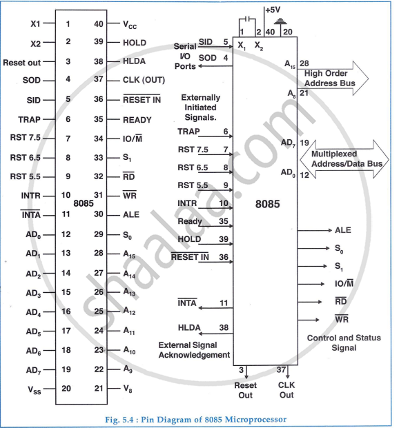
The 8085 Pin Diagram and Functions
The 8085 is housed in a 40 Pin dual - in - line package (DIP). The pinout diagram for 8085 is shown in figure
Multiplexed Address/Data Bus
The signal lines AD7 - AD0 are bidirectional and serve as both the lower order address bus and the data bus. During the early part of an instruction cycle, they act as the address bus, and during the later part, they function as the data bus. This process is called bus multiplexing. The 8085 microprocessor uses a special signal called ALE (Address Latch Enable) to inform peripherals when the address/data bus is sending an address or acting as a data bus.
Control and Status signals
- ALE (Address Latch Enable): This positive pulse is generated each time 8085 starts an operation (machine cycle), indicating that AD1 and AD0 are address bits. It separates address bits.
- RD (Read): This active-low signal indicates that the selected I/O or memory device should be read, and data is available on the data bus.
- WR (Write): This active-low signal indicates that the data on the data bus should be written into the selected memory or I/O location.
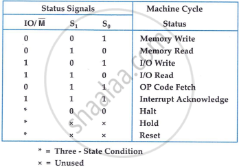
- IO/M: This status signal differentiates between I/O and memory operations. A high signal indicates an I/O operation, while a low signal indicates a memory operation.
- S1 and S0: These status signals identify various operations. The types of machine cycles and corresponding status signals are detailed in the figure.
Externally Initiated signals
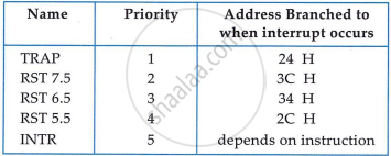
The 8085 microprocessor has five interrupt signals: INTR, RST 7.5, RST 6.5, RST 5.5, and TRAP. These can interrupt program execution.
- INTR: General-purpose interrupt request signal.
- RST 7.5, RST 6.5, RST 5.5: Vectored restart interrupts with priority order as:
- 7.5>6.5>5.5 Have higher priorities than INTR.
- TRAP: Non-maskable interrupt with the highest priority.
- INTA bar: Interrupt acknowledge signal from the microprocessor.
- READY: If low, the microprocessor enters a wait state to synchronize with slower peripherals.
- HOLD: When activated, the microprocessor relinquishes bus control for external peripherals, used in Direct Memory Access (DMA) transfers.
- HLDA: Hold acknowledge signal from the microprocessor.
- RESET IN bar: When low, resets the program counter to zero, tristates buses, and resets the MPU. RESET OUT: Indicates MPU reset and can be used to reset other devices.
Power supply and clock frequency & Serial I/O Ports
- Vcc: +5V power supply.
- Vss: Ground reference.
- X1 and X2: A 6 MHz crystal connects to these pins, with the frequency internally divided by two, resulting in a 3 MHz system operation.
- CLK (OUT): Clock output signal used as the system clock for other devices.
Serial I/O Port: The 8085 has two pins to implement serial transmission, SID (Serial input data) and SOD (serial output data). A single bit can be serially inputted through SID. The output pin SOD is set or reset as per 8085 SIM instruction.
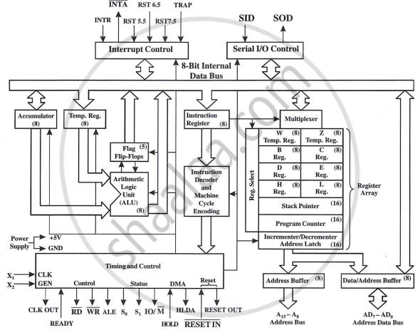
Functional Block diagram of 8085
The block diagram includes the ALU (Arithmetic and logic unit), timing and control unit, Instruction register and decoder, Register array, interrupt control and serial I/O control.
Flags
8085 has five flags.
- S - Sign Flag: After an arithmetic or logic operation, if bit D7 of the result is 1, the sign flag is set to 1. This flag indicates if a number is negative (D7 = 1) or positive (D7 = 0). In signed numbers, D7 shows the sign, and the remaining bits show the magnitude.
- Z - Zero Flag: Set to 1 if the ALU operation results in 0 and reset if the result is not 0. It reflects the results in both the accumulator and other registers.
- AC - Auxiliary Carry Flag: Set when a carry is generated from digit D3 to D4 during an arithmetic operation. It is used internally for BCD (Binary Coded Decimal) operations and is not accessible for programmers
- P - Parity Flag: Checks the number of 1 bits in the accumulator. If the number of 1s is even, the parity flag is set to 1 (even parity). If odd, it is reset to 0 (odd parity). For example, 0000 0011 has even parity.
- CY - Carry Flag: Set if an arithmetic operation results in a carry, otherwise reset. It also acts as a borrow flag for subtraction.

Register Array
The 8085 microprocessor uses both 8-bit and 16-bit registers. It has eight addressable 8-bit registers, six of which can be paired to form 16-bit registers. Additionally, it has two more 16-bit registers.
- BC, DE, and HL are general-purpose registers. They can function as six 8-bit registers or three 16-bit register pairs. BC and DE are typically used for data, while HL is used for address pointing.
- W and Z are temporary 8-bit registers used internally during instruction execution and are not accessible to the programmer.
Program Counter (PC) & Stack Pointer (SP)
Program counter is a 16-bit register used to store the address of the next memory location. It points or directs to the memory location containing the next instruction to be executed. Microprocessor increments the program counter every time it fetches the instruction.
When a subroutine is called, the program counter (PC) jumps to the subroutine's address. Before this, the PC increments by 1 to point to the next main program instruction, saving this address in the stack, a part of RAM. The stack uses PUSH to save the current PC value and adjust the stack pointer. POP retrieves this value, allowing the program to continue from the correct location after the subroutine.
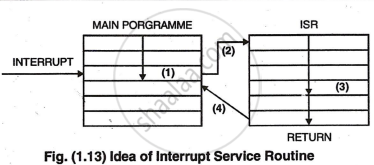
Interrupts
In microprocessor 8085 an interrupt is the input signal which stops the current execution and transfers to specific special routine known as "Interrupt Service Routine" (ISR). After ISR is executed, the microprocessor returns to the program. · "Interrupt" method is employed so that external device can interrupt the microprocessor whenever desired.
The five hardware interrupt inputs are listed in figure.