Topics
Introduction to Microprocessors and Organization of 8085
Instruction Set and Programming of 8085
Introdcution to Inted X-86 Family
Introduction to Microcontroller
Networking Technology
- Introduction to Networking
- Types of Networks
- Multiplexing
- Study of Transmission media
- Coaxial cable (Cable Media)
- Twisted pair cable
- Fiber Optic Cable
- Unbounded (Wireless) Media
- Access Methods
- Network Topologies
- Ethernet (Network Architectures)
- Token-Ring (Network Architectures)
- Internet protocols
- Introduction to connectivity devices
- Definition
- Arithmetic/Logic unit (ALU)
- Registers & Control unit
- Memory & System Bus
- Primary function of the CPU of a microcomputer
- Block diagram of ALU
Microprocessor & its related terms
Definition
A microprocessor is a multipurpose, programmable logic device that reads binary instructions from a storage device called memory, accepts binary data as input and processes data according to those instructions, and provides results as output.
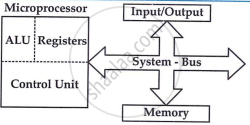
Arithmetic/Logic unit (ALU)
The ALU (Arithmetic Logic Unit) is the microprocessor area where various computing functions are performed. It handles arithmetic operations like addition and subtraction, and logic operations such as AND, OR, and EXCLUSIVE OR. Results are stored in registers or memory.
Registers & Control unit
This area of microprocessor consists of various registers. These registers are used to store data temporarily during a program's execution. Some of the registers are accessible to the user through instructions.
Control Unit: The control unit generates the timing and control signals needed for all microcomputer operations, managing data flow between the microprocessor, memory, and peripherals.
Memory & System Bus
Memory stores binary information, such as instructions and data, and provides it to the microprocessor as needed. To execute programs, the microprocessor reads instructions and data from memory, processes them in the ALU, and either outputs the results or stores them in memory for later use.
The system bus is a communication path between microprocessors and peripherals. It is a group of wires to carry bits. There are several buses in the system.
Primary function of the CPU of amicrocomputer
- To fetch, decode, and execute program instructions in the proper order.
- Transfer data to and from memory and to and from I/O section.
- Respond to external interrupts.
- Provide overall timing and control signals for the entire system.
- R/W of data into memory so bi-directional bus is required.
- All processing and data flow is done in the system with mpu chip.
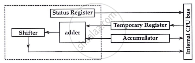
Block diagram of ALU
- ALU is 8 bit
- Accumulator, temporary register, flag register are closely associated with ALU.
- The Temporary register is used to hold data during arithmetic / logic operation.
- Flags are set or reset according to the result of operations in Status register.
- Shifter performs logical operations like rotate left, rotate right etc. Result is placed in accumulator.
- Status registers are Set or Reset according to ALU operation.