Topics
Introduction to Microprocessors and Organization of 8085
Instruction Set and Programming of 8085
Introdcution to Inted X-86 Family
Introduction to Microcontroller
Networking Technology
- Introduction to Networking
- Types of Networks
- Multiplexing
- Study of Transmission media
- Coaxial cable (Cable Media)
- Twisted pair cable
- Fiber Optic Cable
- Unbounded (Wireless) Media
- Access Methods
- Network Topologies
- Ethernet (Network Architectures)
- Token-Ring (Network Architectures)
- Internet protocols
- Introduction to connectivity devices
- Ethernet Frame
- 10 BASE 2 (Ethernet topology)
- 10 BASE 5 (Ethernet topology)
- 10 BASE-T (Ethernet topology)
- 10 BASE – FL; 100 VG - Any LAN & 100 BASE – X (Ethernet topology)
Ethernet (Network Architectures)
Ethernet is a widely used local area network (LAN) architecture based on the CSMA/CD access method, also known as the IEEE 802.3 standard. It can utilize bus or star topologies, with "10" or "100" indicating transmission speeds in Mbps (e.g., 10 BASE 5 for 10 Mbps, 100 BASE-X for 100 Mbps). Ethernet uses baseband transmission, with wiring types designated by "T" for unshielded twisted-pair and "FL" for fiber optics. Data is transmitted in frames, ranging from 64 to 1518 bytes, with 18 bytes used for overhead.
Ethernet Frame
A typical Ethernet II frame has the following sections :
- Preamble A field that signifies the beginning of the frame .
- Address A field that identifies the source and destination address for the frame
- Type: A field that designates the network layer protocol.
- Data: The data being transmitted.
- CRC: Cylindrical redundancy check for error checking.

10 BASE 2 (Ethernet topology)
The 10 BASE 2 Ethernet network uses thinnet cables, with each device connecting to the network via a T-connector attached to the network adapter. Key rules include a minimum 0.5-meter distance between clients, a maximum segment length of 185 meters, and a total network cabling limit of 925 meters. Up to 30 nodes (including clients and repeaters) can be on a segment, with terminators required at both ends. A network may have up to five segments, connected by no more than four repeaters, with only three segments hosting nodes, following the 5-4-3 rule.
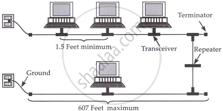
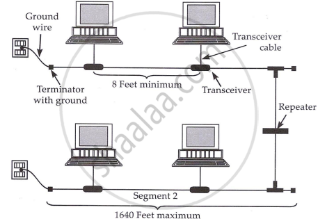
10 BASE 5 (Ethernet topology)
The 10 BASE 5 Ethernet network uses an external transceiver to connect to the network adapter. Network segments are terminated at both ends, with one end grounded. Key rules include a minimum distance of 0.5 meters between transceivers, a maximum segment length of 500 meters, and a total network cabling limit of 2500 meters. Transceiver cables cannot exceed 50 meters, and each network segment can support up to 100 nodes.
10 BASE-T (Ethernet topology)
The 10 BASE-T Ethernet network uses UTP cables in a star topology, where nodes are connected to a central hub that acts as a multiport repeater. This setup is more reliable, easier to manage, and allows for simple troubleshooting, as faulty cable segments can be easily detected and repaired. A problem in one cable only affects the connected device, not the entire network. Key rules include supporting up to 1,024 computers, using UTP category 3, 4, or 5 cables (or STP), a maximum segment length of 100 meters, and a minimum cable distance of 0.5 meters between computers or hubs. 10 BASE-T is flexible and cost-effective for building LANs.

10 BASE – FL; 100 VG - Any LAN & 100 BASE – X (Ethernet Topology)
10 BASE-FL is an Ethernet specification for fiber-optic cables, supporting distances up to 2000 meters and avoiding electrical issues.
100 VG-Any LAN uses demand priority access with two priority levels, connecting computers to child hubs and then to parent hubs. It supports cable lengths up to 250 meters and transmits at 100 Mbps over twisted pairs.
100 BASE-X, or Fast Ethernet, uses a star-bus topology and also operates at 100 Mbps.
