Topics
Introduction to Microprocessors and Organization of 8085
Instruction Set and Programming of 8085
Introdcution to Inted X-86 Family
Introduction to Microcontroller
Networking Technology
- Introduction to Networking
- Types of Networks
- Multiplexing
- Study of Transmission media
- Coaxial cable (Cable Media)
- Twisted pair cable
- Fiber Optic Cable
- Unbounded (Wireless) Media
- Access Methods
- Network Topologies
- Ethernet (Network Architectures)
- Token-Ring (Network Architectures)
- Internet protocols
- Introduction to connectivity devices
- JMP addr & Jcondition addr
- CALL addr & Ccondition addr
- RET(Return) & Rcondition (Conditional return)
- RST n (Restart)
- PCHL (Jump H and L indirect - move H and L to PC)
Branch Instructions
This group of instructions changes the normal program flow. There are two types: unconditional and conditional. Unconditional branch instructions do not test any condition, while conditional branch instructions check the status of a flag to decide whether to execute the branch.
JMP addr & Jcondition addr
In any type of JMP; the control of programme flow is transferred to a memory location within the same programme. It will never go to any other programme or subroutine. While doing so; the microprocessor stores the memory location to which it must jump in Programme Counter:
(PC) <- (byte 3) (byte 2),
JMP addr: This is a three byte instruction. Control is transferred to the instruction whose address is specified byte 3 and byte 2 of current instruction. Addressing Mode: Immediate Addressing
Jcondition addr: This is a three byte instruction. Control is transferred to the instruction whose address is specified byte 3 and byte 2 of current instruction when the said condition becomes true. Addressing Mode: Immediate Addressing
The possible instructions are:
- JNZ addr ......... Jump on Not Zero (Z = 0)
- JZ addr ......... Jump on Zero (Z = 1)
- JNC addr .. ....... Jump on No carry (CY= 0)
- JC addr ......... Jump on carry (CY= 1)
- JPO addr ......... Jump on odd parity (P = 0)
- JPE addr ......... Jump on Even parity (P = 1)
- JP addr ......... Jump on plus (S = 0)
- JM addr ......... Jump on Minus (S = 1)
CALL addr & Ccondition addr
In a CALL instruction, control is transferred to a memory location outside the main program. The microprocessor saves the current memory location of the main program in the stack, allowing it to resume execution from the same point when it returns.
[(SP) - 1] <- (PCH).......PCH= High order eight bits of the next instruction address)
[(SP) - 2] <- (PCL) ........PCL= Low order eight bits of the next instruction address)
(SP) <- (SP) - 2
(PC) <- (byte 3) (byte 2),
CALL addr: This is three byte instruction. 2. Control is transferred to the instruction whose address is specified in byte 3 and byte 2 of current instruction. Addressing Mode: Direct Addressing Mode
Ccondition addr: If the specified condition is true, the actions specified in call instructions are performed; otherwise, control continues sequentially. Addressing Mode: Direct Addressing Mode
- CC= Call on Carry(CY=1)
- CNC= Call on No Carry (CY=0)
- CP= Call on Positive( S=O)
- CM= Call on Minus (S=1)
- CPE Call on Parity Even (P=1)
- CPO Call on Odd Parity (P=0)
- CZ Call on Zero (Z=1)
- CNZ Call on no Zero (Z=0)
RET(Return) & Rcondition (Conditional return)
Both instructions always accompanies the CALL instruction. It instructs the microprocessor to stop the processing and return to the programme. Whenever the RET instruction is executed; this happens:
(PCL) <- [(SP)]
(PCH) <- [(SP)+ 1]
(SP) <- (SP) + 2 ;
This enables the processor to go to the correct position in the main programme from where it has left.
RET: This is a one byte instruction. No flag is affected. Addressing : Register Indirect Addressing.
Rcondition: If the specified condition is true, the actions specified in RET are performed; otherwise the control continues sequentially. This is one byte instruction.
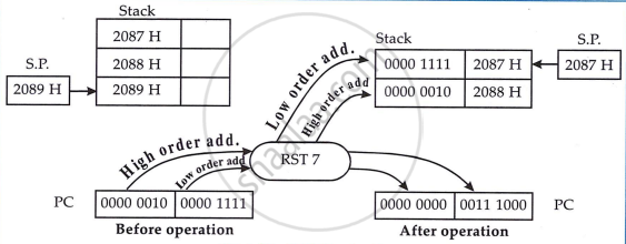
RST n (Restart)
[(SP) - 1] <- (PCH)
[(SP) - 2] <- (PCL)
(SP) <- (SP) - 2
(PC) <- 8 *(NNN)
In this one-byte instruction, the high-order 8 bits of the next instruction address are stored in the memory location at SP-1, and the low-order 8 bits are stored at SP-2. The stack pointer (SP) is decremented by two, and control is transferred to the instruction at the address 8 times the value of NNN. These instructions are used with interrupts. . Addressing : Register Indirect Addressing.
PCHL (Jump H and L indirect - move H and L to PC)
(PCH) <- (H)
(PCL) <- (L)
The content of register H is moved to the high order eight bits of register PC. The content of register L is moved to the low order eight bits of register PC. This is one byte instruction. Addressing Mode: Register Addressing Mode.
