Topics
Introduction to Microprocessors and Organization of 8085
Instruction Set and Programming of 8085
Introdcution to Inted X-86 Family
Introduction to Microcontroller
Networking Technology
- Introduction to Networking
- Types of Networks
- Multiplexing
- Study of Transmission media
- Coaxial cable (Cable Media)
- Twisted pair cable
- Fiber Optic Cable
- Unbounded (Wireless) Media
- Access Methods
- Network Topologies
- Ethernet (Network Architectures)
- Token-Ring (Network Architectures)
- Internet protocols
- Introduction to connectivity devices
- MOV r1, r2; MOV r, M & MOV M, r
- MVI r, data & MVI M, data
- LXI rp, data 16 (Load register pair immediate)
- LDA addr (Load accumulator direct) & STA addr (Store Accumulator Direct)
- LHLD addr(Load Hand L direct) & SHLD addr (Store H and L direct)
- LDAX rp (Load accumulator indirect) & STAX rp (Store accumulator indirect)
- XCHG (Exchange Hand L with D and E)
- IN & OUT
Data Transfer (Copy) group of Instruction
This set of instructions moves data from a source location to a destination location without changing the source data. In technical manuals, this is referred to as data transfer. However, the term 'transfer' can be misleading because it suggests the source data is erased, but it remains unchanged. In every instruction belonging to this group; no flag is affected
MOV r1, r2; MOV r, M & MOV M, r
MOV r1, r2 (Move register): The content of register r2 is moved to register r1. r1 and r2 can be form one of the registers A, B, C, D, E, H, L. This is one byte instruction. For ex: MOV A,B (Contents of B are moved to A). Addressing Mode: Register Direct Addressing
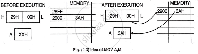
MOV r, M: This is a one-byte instruction where the contents of a memory location, addressed by the H and L registers, are moved to register r. The register r can be any of the following: A, B, C, D, E, H, or L. Addressing Mode: Register indirect Addressing
MOV M, r: It is the opposite of MOV r,M. The content of register r is moved to the memory location whose address is in registers H and L. r can be any one of the registers A, B, C, D, E, H, L. For example: MOV M, C. Here contents of register C are moved to memory pointed by HL pair. Addressing Mode: Register indirect addressing
MVI r, data & MVI M, data
‘I’ in both the instructions refer to ‘immediate’.
MVI r, data: The contents of byte 2 (data) of instruction are moved to register r. This is two byte instruction. First, the op code of the instruction is given and in second byte the data to be transferred is written. For example: MVI A, 82H The data 82 is moved to accumulator. H refers to hexadecimal number system. Addressing: Immediate addressing
MVI M, data: The content of byte 2 of the instruction is moved to memory location whose address is in registers H and L. This is two-byte instruction. It is the same as the previous instruction, the only difference being, here, the data is input into a memory location pointed by HL Pair. For example: MVI M, 12H The data 12 is moved to memory pointed by HL pair. Addressing Mode: Immediate addressing/Register indirect addressing.
LXI rp, data 16 (Load register pair immediate)
(rh) <- (byte 3),
(rl) <- (byte 2),
In a 3-byte instruction, byte 3 is placed in the high-order register (rh) and byte 2 in the low-order register (rl) of a register pair (rp). The register pair rp can be BC, DE, HL, or SP, with rh being the first and rl the second (low-order) register. For example: LXI HL, 4000H. Here 40H is moved to H and 00H is moved to L. Addressing Mode: Immediate addressing
LDA addr (Load accumulator direct) & STA addr (Store Accumulator Direct)
LDA addr: (A)<- [(byte 3) (byte 2)],
The content of the memory location, whose address is specified in byte 2 and byte 3 of the instruction, is moved to register A. This is 3 byte instruction. For example: LDA D000H. The content of memory location D000H is moved to register A. Addressing: Direct Addressing
STA addr: [(byte 3) (byte 2)] <-(A),
This is a 3 byte instruction. The content of accumulator is moved to the memory location whose address is specified in byte 2 and byte 3 of instruction. For example: STA D000H. Contents of accumulator are moved to D000H.
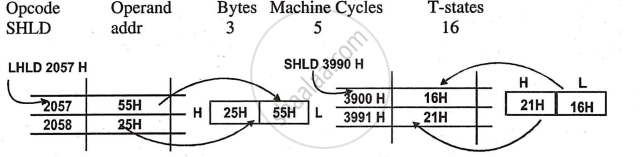
LHLD addr(Load Hand L direct) & SHLD addr (Store H and L direct):
LHLD addr:
(L) <- [(byte 3) (byte 2)]
(H)<- [(byte 3) (byte 2) + 1],
This is a 3 byte instruction. The content of memory location whose address is specified in the byte 2 and byte 3 of the instruction, is moved to register L. The contents of memory location at the succeeding address is moved to register H. Addressing mode: Direct Addressing
For example: LHLD 2100H The content of 2100 are moved to L and 2101 to H.
SHLD addr: [(byte 3) (byte 2)] <- (L)
[(byte 3) (byte 2) + 1] <- (H),
Similar to previous instruction; only difference is the direction of data transfer; data is transferred from L register to the memory location mentioned in the instruction and the content of H register is moved to succeeding memory location. Addressing mode: Direct Addressing
For example: SHLD 4520H. The contents of L are moved to 4520 and that of H to 4521.
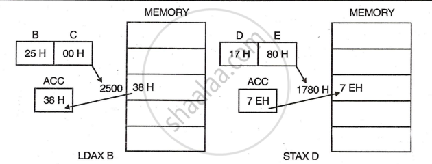
LDAX rp (Load accumulator indirect) & STAX rp (Store accumulator indirect)
LDAX rp: (A) <- [(rp)],
The content of memory location, whose address is in register pair rp, is moved to register A. rp can be B (i.e. B and C) or D (ie D and E). This is one byte instruction. For example : LDAX B. The content of memory location pointed by BC pair is moved to accumulator.
Addressing Mode: Register indirect
STAX rp: [(rp)] <- (A),
Similar to previous instruction; only difference is the direction of data transfer; here the data is transferred from A register to the register pair mentioned in rp. For example : STAX D The contents of A are moved to memory pointed by DE pair. Addressing Mode: Register indirect
XCHG (Exchange Hand L with D and E)
(H) <-> (D)
(L) <-> (E)
The contents of registers H and L are exchanged with the contents of registers D and E. This is one byte instruction. Addressing: Register Addressing Mode.
IN & OUT
IN: Input 8-bit data from an input port to accumulator is part of the I/O instruction group and is two bytes long. The first byte is the operation code for "input data from Port," and the second byte is the 8-bit port address. When executed, the microprocessor sends the 8-bit port address on the lower address bus (A0-A7) and duplicates it on the higher address bus (A8-A15). Either address bus can be decoded to enable the input port. The 8-bit data from the selected port is then loaded into the accumulator, and no flags are affected.
OUT: Output 8-bit data from accumulator to an output port is part of the I/O instruction group and is two bytes long. It works like the IN instruction, but instead of reading data, it transfers 8-bit data from the accumulator to the output port.
